Sealing member, manufacturing method for sealing member and container for electric storage device

A technology for sealing parts and manufacturing methods, applied in the direction of sealing/supporting devices, electrochemical generators, battery pack components, etc., capable of solving problems such as unfavorable economy, gas intrusion, and small volume ratio

Inactive Publication Date: 2014-10-22
FUJIMORI KOGYO CO LTD
View PDF3 Cites 7 Cited by
  • Summary
  • Abstract
  • Description
  • Claims
  • Application Information

AI Technical Summary

Problems solved by technology

However, for containers for electrical storage devices using aluminum laminated packaging materials, if the aluminum laminated packaging material is drawn deeply in order to increase the volume ratio, there is a problem that pores will be generated on the aluminum foil, resulting in water vapor or oxygen and other gases invaded from the outside
[0007] However, in order to use an infrared laser, it is necessary to mix an infrared laser absorber with the resin constituting the cylindrical member or the cover, which is economically disadvantageous.
In addition, since the container for an electrical storage device in Patent Document 1 or 2 has a thick resin cylindrical member, the volume ratio is small.

Method used


Image

  • Sealing member, manufacturing method for sealing member and container for electric storage device
  • Sealing member, manufacturing method for sealing member and container for electric storage device
  • Sealing member, manufacturing method for sealing member and container for electric storage device

Examples


Embodiment

[0134] Below, refer to Figure 1~3 The present invention will be described in detail based on examples, but the present invention is not limited thereto.

[0135]

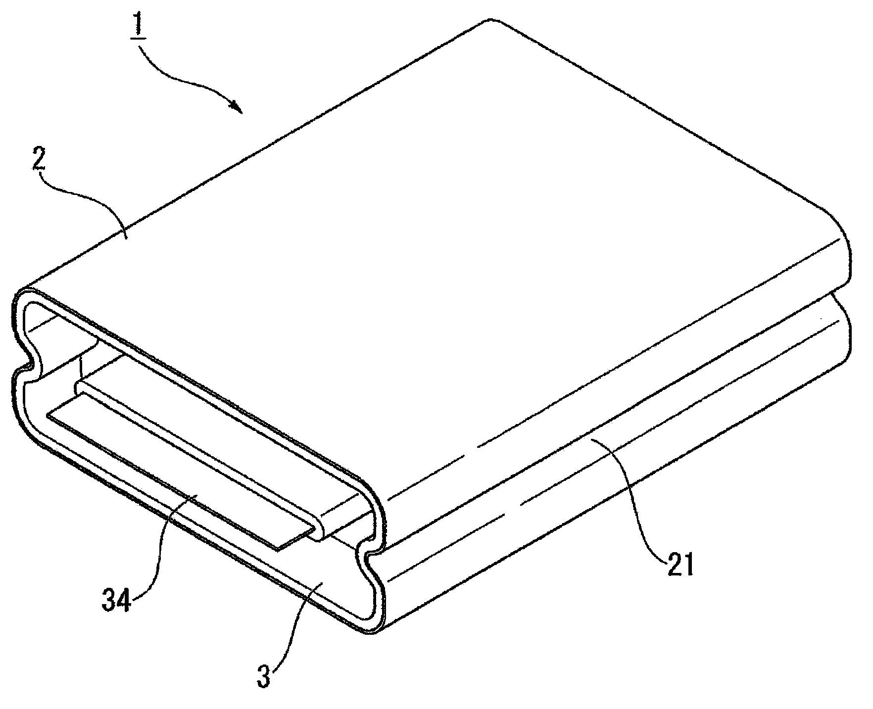
[0136] Metal foil made of 12 μm aluminum foil and a sealant layer made of 60 μm non-stretched PP film are dry-laminated on one side of a 15 μm biaxially stretched nylon 6 film using a polyurethane-based adhesive to obtain a metal Laminated film of foil. The laminated film was cut into a rectangle of 60 mm x 130 mm. With the sealant layer of the laminated film cut into a rectangle as the inside, the two ends of the short sides overlap each other by 10 mm and are welded together to form a palm-shaped sealing part (not shown), thereby producing the cylindrical film 2 . The palm-shaped sealing portion is creased so as to overlap the unwelded cylindrical diaphragm 2 .

[0137]

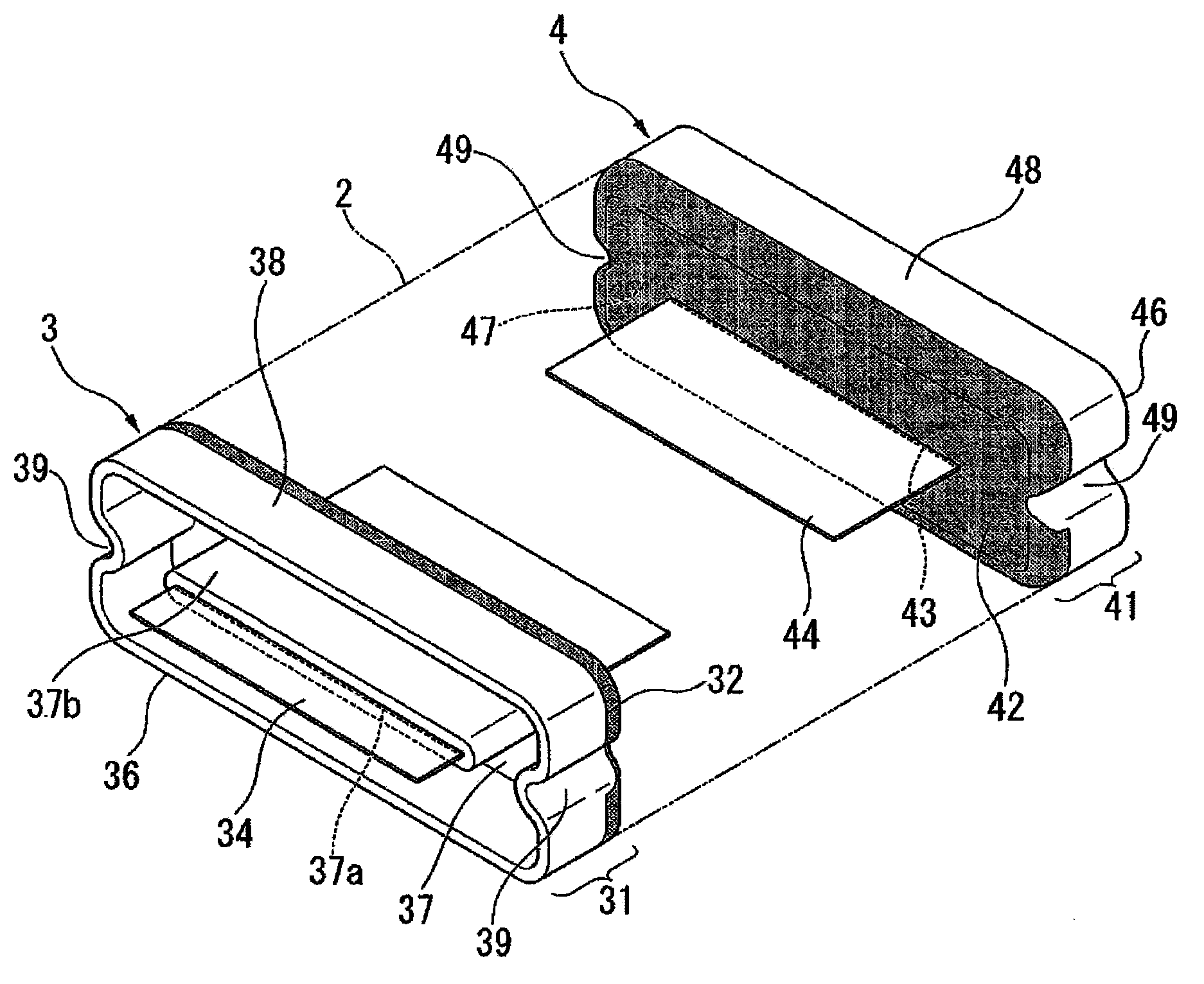
[0138]As electrode members, a positive electrode member 34 made of aluminum foil with a length of 25 mm, a width of 25 mm, and a thickne...


PUM

PropertyMeasurementUnit
thicknessaaaaaaaaaa
thicknessaaaaaaaaaa
thicknessaaaaaaaaaa

Abstract

The invention provides a sealing member, a manufacturing method for the sealing member and container for an electric storage device. The sealing member is high in production efficiency, has relatively high gas barrier property of uneasily enabling steam or oxygen or other gases to penetrate, and is applied to the end part of a sealing cylindrical diaphragm. The sealing member comprises a tinsel formed body (32), a resin formed body (36) and a plate-shaped or rod-shaped electrode member (34); the outer surface of the tinsel formed body (32) is provided with a welding connection layer welded to the inner surface of the end part of the cylindrical diaphragm, the middle part of the tinsel formed body (32) is provided with a tinsel, and the inner surface of the tinsel formed body (32) is provided with an adhesive resin layer, and the tinsel formed body (32) also is provided with a thorough hole penetrating the welding connection layer, the tinsel and the adhesive resin layer; the resin formed body (36) is provided with a sealing wall and an annular sidewall, the sealing wall is adhered to the adhesive resin layer and forms a sealing face of the main face for sealing the end part of the cylindrical diaphragm, the sidewall and the sealing wall continuously reinforce the tinsel formed body; and the middle part of the electrode member (34) is provided with an insulating part around covered by an insulating layer, and the insulating part of the electrode member is inserted into the thorough hole of the tinsel formed body and is tightly fixed by the resin formed body.

Description

technical field [0001] The present invention relates to a sealing member usable in a container for an electrical storage device for accommodating a power generating element, a method for manufacturing the sealing member, and a container for an electrical storage device in which the sealing member is welded. Background technique [0002] Conventionally, metal containers having excellent water vapor permeation resistance have been widely used as containers for electric storage devices that house power generation elements of electric storage devices such as lithium-ion rechargeable batteries and capacitors. However, metal containers are heavy and bulky, and the packaging process is complicated, so productivity is low. In particular, welding between the container main body and the lid body requires a lot of labor and has problems from the viewpoint of mass productivity. In addition, with regard to rechargeable batteries such as lithium batteries for electric vehicles, since the...

Claims


Application Information

Patent Timeline
Patent Type & Authority Applications(China)
IPC IPC(8): H01M2/02H01M2/08H01M50/172H01M50/188
CPCH01M8/028H01M8/0286Y02E60/50
Inventor 饭塚宏和佐藤考勇金田康宏武井邦浩
Owner FUJIMORI KOGYO CO LTD
Why Eureka
Try Eureka