Drainage pipe

A drainage tube and square tube technology, applied in the field of medical devices, can solve the problems of poor drainage, difficulty in achieving the purpose of drainage, increasing the probability of intracranial infection of patients, etc., achieving simple operation, smooth drainage process, and reducing intracranial infection. the effect of the probability of

Inactive Publication Date: 2014-10-29
徐増良
View PDF5 Cites 2 Cited by
  • Summary
  • Abstract
  • Description
  • Claims
  • Application Information

AI Technical Summary

Problems solved by technology

[0002] Intracranial hematoma caused by craniocerebral injury is mostly compound type, epidural, subdural and cerebral contusion exist at the same time, or compound subdural hematoma often requires subdural and epidural drainage at the same time after operation. A single intracranial drainage tube is placed in the subdural space and the epidural space, and the blood in the two spaces mixes with each other, and the ordinary drainage tube is not pressure-resistant and easy to break, resulting in unsmooth drainage and difficult to achieve the purpose of drainage. 、Multiple drainage tubes increase the workload of nursing staff and the difficulty of nursing, and at the same time increase the probability of intracranial infection in patients

Method used


Image

  • Drainage pipe
  • Drainage pipe
  • Drainage pipe

Examples


Embodiment 1

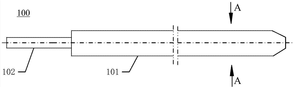
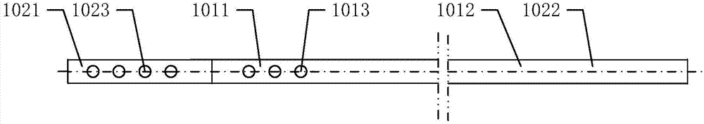
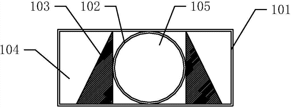
[0025] Such as Figure 1-3 As shown, the first drainage tube 101 is formed in the form of an outer tube, the second drainage tube 102 is formed in the form of an inner tube, and the second drainage tube 102 and the pressure-resistant strip 103 are located inside the first drainage tube 101 , preferably, the first drainage tube 101 is flat, for example, its cross-section can be a rectangle, oval or drum-shaped ring, the cross-section of the second drainage tube 102 is preferably a ring, and the second drainage tube 102 is preferably circular. The longitudinal axis of the tube 102 coincides with the longitudinal axis of said first drainage tube 101 . When the cross-section of the first drainage tube 101 is a rectangular ring, the four edges of the first drainage tube 101 are chamfered to form a smooth arc-shaped transition fillet, so as to avoid harm to the human body when the drainage tube contacts the human body . The diameter of the second drainage tube 102 is slightly smal...

Embodiment 2

[0028] Such as Figure 4-6 As shown, the first drainage tube 101 and the second drainage tube 102 are both round tubes or square tubes (shown as a round tube in the figure), and the first drainage tube 101 and the second drainage tube 102 are arranged side by side at a certain distance. placed, the pressure-resistant strip 103 is located between the first drainage tube 101 and the second drainage tube 102, the cross-sectional dimensions of the first drainage tube 101 and the second drainage tube 102 are the same, the first drainage tube 101 and the second drainage tube 101 The drainage tube 102 is arranged symmetrically with respect to the pressure bar 103 . When the first drainage tube 101 and the second drainage tube 102 are both square tubes, the two outer edges thereof are inverted into a circular arc shape, so as to avoid harming the human body when the drainage tube comes into contact with the human body. In this embodiment, the length of the pressure-resistant strip 10...


PUM


Abstract

The invention relates to a drainage pipe. The drainage pipe comprises a first drainage pipe, a second drainage pipe and a pressure-resistant strip, wherein the first drainage pipe comprises a first drainage cavity, the second drainage pipe comprises a second drainage cavity, and the first drainage cavity is not communicated with the second drainage cavity; the first drainage pipe comprises a first inserting section and a first main body section, the second drainage pipe comprises a second inserting section and a second main body section; a plurality of lateral holes are evenly distributed in the first inserting section and the second inserting section; the main body section of the first drainage pipe and the main body section of the second drainage pipe are integrated; the pressure-resistant strip is located between the main body section of the first drainage pipe and the main body section of the second drainage pipe. The drainage pipe can carry out drainage simultaneously on an interval outside a hard film and an interval under the hard film, will not bend partially in the drainage process, is smooth in the drainage process, is easy to operate and largely reduces the possibility that a patient has an intracranial infection.

Description

technical field [0001] The invention relates to the technical field of medical appliances, in particular to a special pressure-resistant double-chamber epidural and lower drainage tube for neurosurgery. Background technique [0002] Intracranial hematoma caused by craniocerebral injury is mostly compound type, epidural, subdural and cerebral contusion exist at the same time, or compound subdural hematoma often requires subdural and epidural drainage at the same time after operation. A single intracranial drainage tube is placed in the subdural space and the epidural space, and the blood in the two spaces mixes with each other, and the ordinary drainage tube is not pressure-resistant and easy to break, resulting in unsmooth drainage and difficult to achieve the purpose of drainage. 1. The drainage of multiple drainage tubes increases the workload and nursing difficulty of the nursing staff, and simultaneously increases the probability of intracranial infection of the patient....

Claims


Application Information

Patent Timeline
Patent Type & Authority Applications(China)
IPC IPC(8): A61M25/14
Inventor 徐増良匡如宋同勋綦淑杰杨青
Owner 徐増良
Why Eureka
Try Eureka