Splicing joint at steel plate combined shear wall variable section

A combined shear wall and variable section technology, applied in the direction of walls, building components, buildings, etc., can solve the problems of prolonging the construction period, consuming man-hours, increasing the installation time, etc., so as to improve the construction progress, reduce the construction cost, and improve the construction. The effect of efficiency

Pending Publication Date: 2018-03-06
HANGXIAO STEEL STRUCTURE
View PDF7 Cites 1 Cited by
  • Summary
  • Abstract
  • Description
  • Claims
  • Application Information

AI Technical Summary

Problems solved by technology

In these types of steel plate composite shear wall splicing joints, one of the more difficult problems is that there are usually stiff plates inside the steel plate composite shear wall that cannot be welded inside, which leads to the discontinuity of the stiff plates at the joints and the appearance of weak areas. The problem, therefore, needs to be solved by relevant strengthening measures, and the main method currently used is to insert steel bars inside the steel plate composite shear walls at the nodes for reinforcement, such as figure 1 As shown, the reinforcement at the node is carried out by setting a partition 4 between the lower steel plate combined shear wall 1 and the upper steel plate combined shear wall 2, and by setting the ribs 10 penetrating through the upper and lower steel plate combined shear walls
This measure has the following problems: 1. The amount of steel bars is large, which is uneconomical; 2. Since the top plate at the joint is a square hole in the middle, the size itself is small, and the inserted steel bars further occupy the open space, making the combination of steel plates shear It is more difficult for the force wall to pour the internal concrete, which affects the compactness of the concrete pouring; 3. The steel bar insertion type needs to fix the steel bar, and this part of the fixing work takes a lot of man-hours; 4. When the steel plate wall is hoisted, insert the steel bar It is easy to be touched by the steel plate, which will cause the steel bar to bend, hinder the hoisting of the steel plate wall, increase the difficulty of installation, increase the installation time, and prolong the construction period; Hidden danger

Method used


Image

  • Splicing joint at steel plate combined shear wall variable section
  • Splicing joint at steel plate combined shear wall variable section
  • Splicing joint at steel plate combined shear wall variable section

Examples


Embodiment Construction

[0037] The present invention will be described in detail below in conjunction with the embodiments and the accompanying drawings. It should be noted that the described embodiments are only intended to facilitate the understanding of the present invention, rather than limiting it in any way.

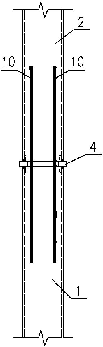
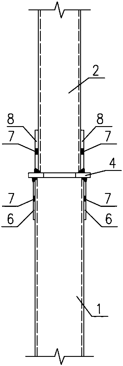
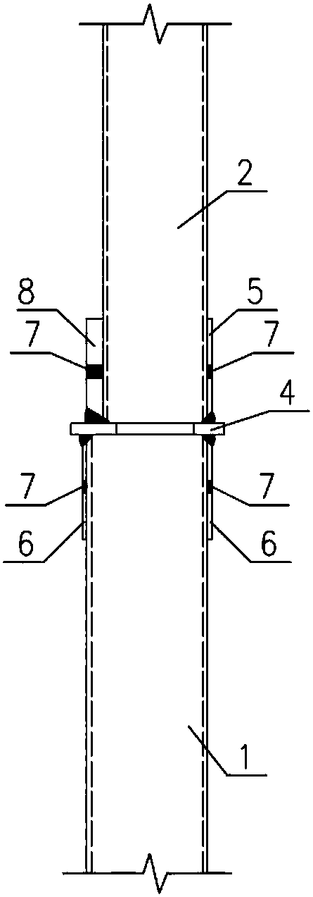
[0038] see Figure 2-11 As shown, the splicing joint at the variable section of a steel plate combined shear wall provided in this embodiment includes an upper steel plate combined shear wall 2 and a lower steel plate combined shear wall 1, and the upper steel plate combined shear wall 2 and the lower steel plate A partition plate 4 is arranged between the combined shear walls 1; an upper reinforcing plate 5 is arranged on the bottom outer surface of the side of the upper steel plate combined shear wall 2, and the top of the side of the lower steel plate combined shear wall 1 The outer surface is provided with a lower reinforcing plate 6; the upper steel plate combined shear wall 2 and th...


PUM


Abstract

The invention relates to a splicing joint at a steel plate combined shear wall variable section. The splicing joint comprises an upper steel plate combined shear wall and a lower steel plate combinedshear wall. A partition plate is arranged between the upper steel plate combined shear wall and the lower steel plate combined shear wall. The width of the upper steel plate combined shear wall is different from the width of the lower steel plate combined shear wall. The upper steel plate combined shear wall is provided with an upper reinforced plate. The lower steel plate combined shear wall is provided with a lower reinforced plate. The thickness of the upper reinforced plate is different from that of the lower reinforced plate. The upper steel plate combined shear wall, the lower steel plate combined shear wall, the upper reinforced plate and the lower reinforced plate are fixedly connected with the partition plate. A through hole is formed in the middle of the partition plate, and theposition of the through hole corresponds to a cavity of a steel plate combined shear wall. The splicing joint has the beneficial effects that by arranging the thickened reinforced plates, the load ofthe upper steel plate combined shear wall is effectively transmitted to the lower steel plate combined shear wall by the thickened reinforced plates, and the upper steel plate combined shear wall is arranged to be tightly attached to a side plate; and meanwhile, by arranging a plugging and welding hole, it is ensured that local bending and bulge cannot appear in the reinforced plates , and workshop making is facilitated.

Description

technical field [0001] The invention relates to the field of building structures, in particular to a splicing joint at a variable section of a steel plate composite shear wall. Background technique [0002] At present, steel structures are used more and more in the field of building structure technology, and various new steel structures are emerging, which have been applied in the engineering field, and the number is also rising, with broad prospects. Its main advantages are: compared with concrete building structures, it has better applicability and feasibility. Such as reducing the volume of components, increasing the use of space; reducing the weight of the structure, reducing or completely eliminating the formwork and support required for construction; reducing embedded parts, improving seismic performance; facilitating construction and shortening the construction period. Compared with steel structures, it can save more steel, improve the stability and torsional perform...

Claims


Application Information

Patent Timeline
Patent Type & Authority Applications(China)
IPC IPC(8): E04B2/00E04B1/61
CPCE04B1/6116E04B2/00
Inventor 徐韶锋单银木刘晓光石柏林易建文束炜陈鹏高小强汤文锋谢优胜骆贵波李毅刘重阳李庆刚
Owner HANGXIAO STEEL STRUCTURE
Why Eureka
Try Eureka