
An anti-freezing device using an air-water nozzle

An air-water nozzle and anti-freezing technology, applied in water conservancy projects, water conservancy engineering equipment, buildings, etc., can solve problems such as maintenance difficulties, loosening of protective blocks, and reduction of durability of buildings (structures) to achieve equipment maintenance. Convenience, avoid destructive effect, clear ice-breaking effect

Active Publication Date: 2015-10-28
辽宁省水利水电科学研究院有限责任公司
View PDF9 Cites 0 Cited by
  • Summary
  • Abstract
  • Description
  • Claims
  • Application Information

AI Technical Summary

Problems solved by technology

[0002] On the water-facing side of hydraulic structures (structures) in the north, they are subjected to freezing every winter. Repeated freeze-thaw cycles will lead to damages such as concrete freeze-thaw denudation and loosening of protective blocks on the water-retaining surface buildings (structures). Reduced durability of buildings (structures)
For the gate part, the static ice pressure caused by the expansion of the ice sheet will cause the gate to deform, lift up, and even cause structural damage, resulting in the consequences of the gate being unable to open and close normally, and water sealing failure.
Currently commonly used anti-freezing measures, such as compressed air method, submersible pump method, heat pipe anti-freezing method and manual slotting ice-breaking method, etc., generally have many problems such as high energy consumption, dangerous operation and difficult maintenance during operation.

Method used


Image

  • An anti-freezing device using an air-water nozzle
  • An anti-freezing device using an air-water nozzle
  • An anti-freezing device using an air-water nozzle

Examples


Embodiment 1

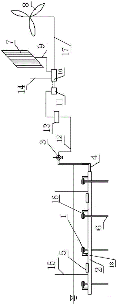
[0029] An anti-freezing device using air-water sprinklers, comprising fifty first air-water sprinklers, fifty second air-water sprinklers, a dry pipe 2 and a blower fan 3. The first air-water shower head 1 and the second air-water shower head 17 have the same structure.

[0030] The first air-water spray head includes a first spray head 1 and a first water suction pipe 6 . The water outlet port of the first water suction pipe 6 communicates with the fluid channel in the first spray head 1 .

[0031] The second air-water spray head includes a second spray head 16 and a second water suction pipe. The water outlet port of the second water suction pipe communicates with the fluid channel in the second spray head 16 .

[0032] Fifty first spray heads 1 and fifty second spray heads 16 are installed on the dry pipe 2, and the axes of the fifty first spray heads 1 and fifty second spray heads 16 are parallel to the axis of the dry pipe 2 . Each first spray head 1 communicates with...

Embodiment 2

[0058] Embodiment 2 is basically the same as Embodiment 1, and its difference is:

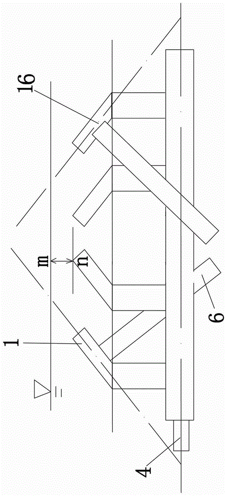
[0059] The acute angles formed by the axes of the fifty first nozzles 1 and the axis of the main pipe 2 are all 45°.

[0060] The acute angles formed by the axes of the fifty first nozzles 1 and the water surface are all 45°.

[0061] The axes of the fifty first nozzles 1 form an acute angle of 45° with the horizontal plane at the inlet of each corresponding first nozzle at the same time, and are located above the horizontal plane at the inlet of the first nozzle.

[0062] The acute angles formed by the axes of the fifty second nozzles 16 and the axis of the main pipe 2 are all 45°.

[0063] The acute angle formed by the axes of the fifty second nozzles 16 and the water surface is 45°.

[0064] The axes of the fifty second nozzles 16 form an acute angle of 45° with the horizontal plane at the inlet of the corresponding second nozzle, and are located above the horizontal plane at the inlet of ...

Embodiment 3

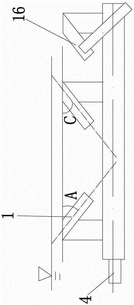
[0070] Embodiment 3 is basically the same as Embodiment 2, except that: the axis of the first spray head 1 is arranged symmetrically with the horizontal plane at the entrance of the first spray head described in Embodiment 2.

[0071] The angle A between the axis of the first spray head 1 and the horizontal plane at the entrance of the first spray head is -45°, which is located below the horizontal plane at the entrance of the first spray head.

[0072] The axis of the second spray head 16 is arranged symmetrically with the horizontal plane at the inlet of the second spray head described in Embodiment 2.

[0073] The angle C between the axis of the second spray head 16 and the horizontal plane at the entrance of the second spray head is -45°. Such as image 3 , below the water level at the inlet of the second nozzle.

[0074] The axes of the fifty first spray heads 1 , the axes of the fifty second spray heads 16 and the axis of the main pipe 2 are all located in a vertical p...


PUM


Abstract

A freezing preventing device with air water sprayers comprises a plurality of first air water sprayers and a plurality of second air water sprayers. Each first air water sprayer comprises a first sprayer body and a first water suction pipe, wherein the water outlet end of the first water suction pipe is communicated with a fluid channel in the first sprayer body. The second air water sprayers are the same in structure. The first sprayer bodies and second sprayer bodies are installed on a main pipe. A draught fan is connected with the main pipe through an air supply pipe. The main pipe is provided with a floating barrel. The draught fan is connected with the output end of a clean energy and commercial power combined power supply device through a power cable. When the axis of the main pipe is horizontally arranged, the horizontal planes of inlets of the first sprayer bodies are located on the horizontal plane where the axis of the main pipe is located and the area above horizontal plane where the axis of the main pipe is located. The angle formed between the axes of the first sprayers and the horizontal planes of the inlets of the first sprayer bodies ranges from -45 degrees to 45 degrees, and the second air water sprayers are the same in structure. The non-frozen area can be formed on the upstream side of a gate and other hydraulic structures in the northern area, and equipment is convenient to maintain.

Description

Technical field [0001] The present invention belongs to the field of water conservancy engineering anti -freezing device. It specially involves a anti -frozen device with gas water noble heads. It is suitable for water -building (structure) manufacturers to welcome the water side of the water side in winter, especially suitable for preventing the water surface in front of the gate. Background technique [0002] On the side of the northern aquatic construction (structure) building, the frozen effect will be affected every winter. Repeated freezing and merging cycle will lead to the destruction of concrete frozen melting and erosion of concrete and stones in the construction of the water blocking surface (structure).Reduce the durability of the building (structure).For the gate of the gate, the static ice pressure caused by the expansion of the ice sheet will cause the gate to deform, lift, and even cause structural destruction, causing the gate to unable to open and close, and sto...

Claims


Application Information

Patent Timeline
Patent Type & Authority Patents(China)
IPC IPC(8): E02B1/00
Inventor 李志祥宋立元汪玉君夏海江汪魁峰宗兆博胡庆华苏炜焕刘波艾新春王兴华马洪山臧志刚富天生周旭吴硕张欣杨毅刘柳
Owner 辽宁省水利水电科学研究院有限责任公司
Learn More