
A sawtooth weir groove anti-freezing device

An anti-freezing, weir and groove technology, applied in water conservancy projects, open-air water surface cleaning, construction, etc., can solve the problems of loose protective block stones, concrete freeze-thaw erosion, maintenance difficulties, etc., to meet self-sufficient operation, avoid direct Destructive effect, the effect of small operation and maintenance

Inactive Publication Date: 2015-09-30
辽宁江河水利水电新技术设计研究院有限公司
View PDF8 Cites 0 Cited by
  • Summary
  • Abstract
  • Description
  • Claims
  • Application Information

AI Technical Summary

Problems solved by technology

[0002] On the water-facing side of hydraulic structures (structures) in the north, they are subjected to freezing every winter. Repeated freeze-thaw cycles will lead to damages such as concrete freeze-thaw denudation and loosening of protective blocks on the water-retaining surface buildings (structures). Reduced durability of buildings (structures)
For the gate part, the static ice pressure caused by the expansion of the ice sheet will cause the gate to deform, lift up, and even cause structural damage, resulting in the consequences of the gate being unable to open and close normally, and water sealing failure.
Currently commonly used anti-freezing measures, such as compressed air method, submersible pump method, heat pipe anti-freezing method and manual slotting ice-breaking method, etc., generally have many problems such as high energy consumption, dangerous operation and difficult maintenance during operation.

Method used


Image

  • A sawtooth weir groove anti-freezing device

Examples


Embodiment 1

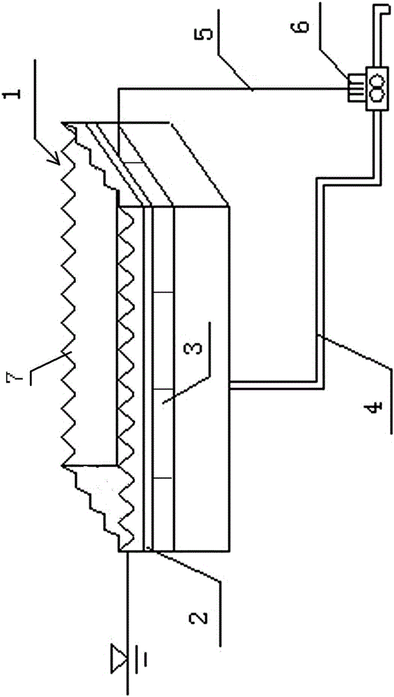
[0018] A saw-tooth weir-groove anti-freezing device comprises a saw-tooth weir-groove 1, a plurality of buoys 3 and a hydroelectric generator 6.

[0019] The sawtooth weir flume 1 includes a weir flume body and a plurality of saw teeth 7, and the plurality of saw teeth 7 are arranged on the edge of the opening of the weir flume body, and form an integral structure with the weir flume body.

[0020] A plurality of buoys 3 are fixed around the surface of the outer wall of the weir tank by bolts. The bottom of the weir tank body is connected with the hydroelectric generator 6 through the drain pipe 4 .

[0021] An electric heating device 2 is fixed around the surface of the outer wall of the weir tank at the same time. The electric heating device 2 is connected with a hydroelectric generator 6 through a cable 5 .

[0022] The electric heating device 2 and the hydroelectric generator 6 are known technologies, so the description will not be repeated.

[0023] The electric heatin...

Embodiment 2

[0029] Embodiment 2 is basically the same as Embodiment 1, except that the electric heating device 2 is an electric heating wire.


PUM


Abstract

A sawtooth-weir-groove-shaped anti-freezing device comprises a sawtooth weir groove, a plurality of pontoons and a hydroelectric generator. The edge of an upper opening in a weir groove body of the sawtooth weir groove is provided with a plurality of sawteeth integrated with the weir groove body, the pontoons are fixed around the surface of the outer wall of the weir groove body, and the bottom of the weir groove body is connected with the hydroelectric generator through a water drain pipe. Electric heating devices are fixed around the surface of the outer wall of the weir groove body and connected with the hydroelectric generator through cables. The sawtooth weir groove is formed in the upstream side of a water gate and other hydraulic structures and floats on the water surface, water flow on the surface enters the weir groove through pits of the sawteeth of the upper opening in the weir groove body, and the water flow drained through the water drain pipe drives the hydroelectric generator to supply power to the electric heating devices, so that the outer wall of the sawtooth weir groove is heated, and the water surface around the sawtooth weir groove is prevented from freezing. In this way, it can be ensured that the water surface within a certain range on the upstream side of the water gate or the other hydraulic structures does not freeze, and the anti-freezing purpose is achieved.

Description

technical field [0001] The invention belongs to the winter anti-freezing device in the field of water conservancy engineering, and in particular relates to a sawtooth weir-groove anti-freezing device, which can be applied to the water-facing side of a hydraulic construction (structure), and is especially suitable for being installed in front of a gate to prevent freezing of the water surface. Background technique [0002] On the water-facing side of hydraulic structures (structures) in the north, they are subjected to freezing every winter. Repeated freeze-thaw cycles will lead to damages such as concrete freeze-thaw denudation and loosening of protective blocks on the water-retaining surface buildings (structures). Reduced the durability of buildings (structures). For the gate part, the static ice pressure caused by the expansion of the ice sheet will cause the gate to deform, lift up, and even cause structural damage, resulting in the failure of the gate to open and close ...

Claims


Application Information

Patent Timeline
Patent Type & Authority Patents(China)
IPC IPC(8): E02B15/02
Inventor 汪玉君李志祥宋立元汪魁峰夏海江宗兆博刘大为谭丽娥苏炜焕阴国旗马洪山张永先王兴华张欣杨毅刘柳李远姜涛唐树新汤彦明
Owner 辽宁江河水利水电新技术设计研究院有限公司
Learn More