Electromagnetic shielding connector structure

An electromagnetic shielding and connector technology, which is applied in the direction of connection, two-part connection device, and parts of the connection device, can solve the problems of easy shaking, poor coordination between male and female, time-consuming and laborious disassembly of male or female plug structures, etc. Problems, to achieve the effect of smooth plugging, good fit, quick and convenient disassembly

Active Publication Date: 2014-10-29
XIAMEN WAIN ELECTRICAL
View PDF5 Cites 5 Cited by
  • Summary
  • Abstract
  • Description
  • Claims
  • Application Information

AI Technical Summary

Problems solved by technology

[0002] The existing electromagnetic shielding connector has a structure such as figure 1 As shown, it includes the matching male plug part A and the female plug part B. The structures of the male plug part and the female plug part are two halves, which are connected by hooks. However, the two halves of the male plug or female plug structure It is time-consuming and labor-intensive to disassemble. It is quite troublesome to hit the hook or use tools to complete the disassembly. Moreover, the two-half structure is easy to shake from side to side, and the male-female fit is poor.
[0003] At present, the frame of the electromagnetic shielding connector fixing plug is also two-half, using a hinge structure. The Chinese document CN1191400A discloses a fixed frame, which is composed of two half-frames hinged to each other, and the two-half frame structure is in the It is also easy to shake when the connector is mated

Method used


Image

  • Electromagnetic shielding connector structure
  • Electromagnetic shielding connector structure
  • Electromagnetic shielding connector structure

Examples


Embodiment

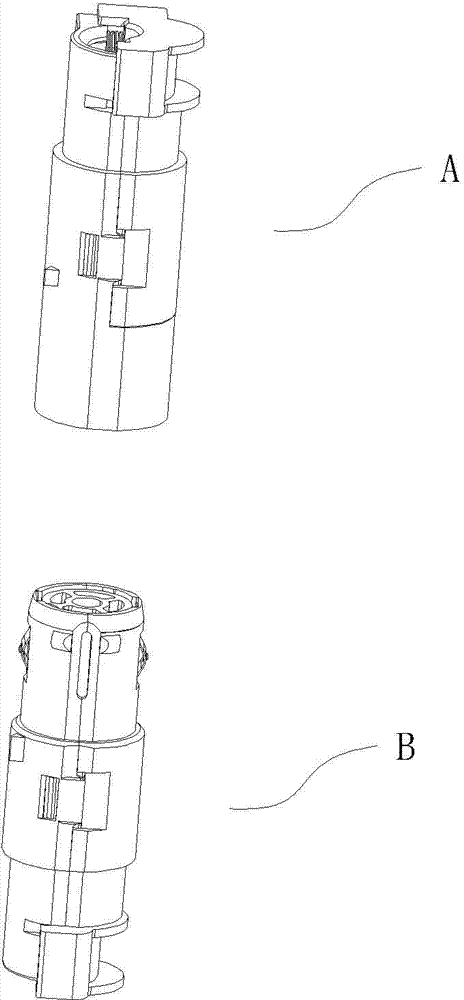
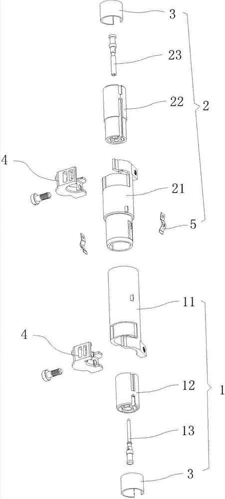
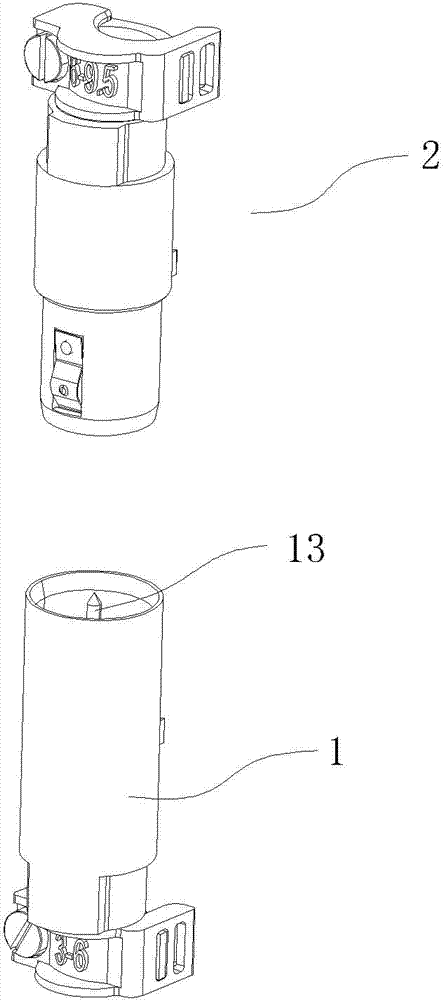
[0031] Example: see Figure 2 to Figure 5 , the electromagnetic shielding connector structure of the present invention is composed of a male plug 1 and a female plug 2, wherein:

[0032] Male plug 1, which includes an electromagnetic shielding shell (male) 11, a male plug body 12, a male pin 13, an opening pressure ring 3 and a fixing block 4, and the electromagnetic shielding shell 11 places a male plug body 12, a male pin 13 and an opening The pressure ring 3, wherein the pins are placed in the insert body, the open pressure ring 3 is placed on the upper end of the insert body and the fixed block 4 is locked at the port of the shell to fix the insert body;

[0033] The female plug 2 includes an electromagnetic shielding shell (female) 21, a female plug body 22, a female pin 23, an opening pressure ring 3 and a fixing block 4, and the female plug body 22, the female pin 23 and the opening are placed in the electromagnetic shielding shell 21 The pressure ring 3, wherein the p...


PUM


Abstract

The invention provides an electromagnetic shielding connector structure. The electromagnetic shielding connector structure consists of a male plug and a female plug, wherein each plug mainly comprises an electromagnetic shielding shell, a plug body, a pin, an opening compression ring and a fixing block; each plug body, the corresponding pin and the corresponding opening compression ring are placed in the corresponding electromagnetic shielding shell; each pin is placed in the corresponding plug body; each opening compression ring is placed on the upper end surface of the corresponding plug body; each fixing block is locked on a port of the corresponding shell so that the corresponding plug body is fixed; and connecting ends which are matched with each other are respectively arranged on the male plug and the female plug, so that the pins in the male plug and the female plug can be connected with each other. The electromagnetic shielding connector structure is applied to a frame assembling unit, so that a plurality of pairs of pin circuits are connected to one another. The electromagnetic shielding connector structure is multifunctional; and a quick connection purpose is achieved.

Description

technical field [0001] The invention discloses an electromagnetic shielding connector structure, which belongs to the technical field of electrical connector manufacturing according to the International Patent Classification (IPC). Background technique [0002] The existing electromagnetic shielding connector has a structure such as figure 1 As shown, it includes the matching male plug part A and the female plug part B. The structures of the male plug part and the female plug part are two halves, which are connected by hooks. However, the two halves of the male plug or female plug structure It is time-consuming and laborious to disassemble, and it is quite troublesome to hit the hook or use tools to complete the disassembly, and the two-half structure is easy to shake from side to side, and the male-female fit is poor. [0003] At present, the frame of the electromagnetic shielding connector fixing plug is also two-half, using a hinge structure. It is also easy to shake wh...

Claims


Application Information

Patent Timeline
Patent Type & Authority Applications(China)
IPC IPC(8): H01R13/6581H01R13/639H01R24/84
Inventor 罗奕奕吴志伟蓝惠中
Owner XIAMEN WAIN ELECTRICAL
Why Eureka
Try Eureka