
Active brake pedal travel simulator and control method thereof

A stroke simulator, brake pedal technology, applied in the direction of brakes, foot start devices, brake transmission devices, etc., can solve the problems of exceeding the performance requirements of the hydraulic adjustment unit, insufficient utilization of component resources, etc., to increase flexibility and accuracy, complete functionality, and improved economy

Inactive Publication Date: 2013-06-26
JILIN UNIV
View PDF15 Cites 38 Cited by
  • Summary
  • Abstract
  • Description
  • Claims
  • Application Information

AI Technical Summary

Problems solved by technology

[0006] The technical problem to be solved by the present invention is to overcome the problems in the prior art that the performance requirements of the hydraulic adjustment unit exceed the capabilities of existing products, and the utilization of existing component resources is still insufficient, and provide an active braking system. Pedal stroke simulator and its control method

Method used


Image

  • Active brake pedal travel simulator and control method thereof
  • Active brake pedal travel simulator and control method thereof
  • Active brake pedal travel simulator and control method thereof

Examples


Embodiment Construction

[0040] The present invention is described in detail below in conjunction with accompanying drawing:

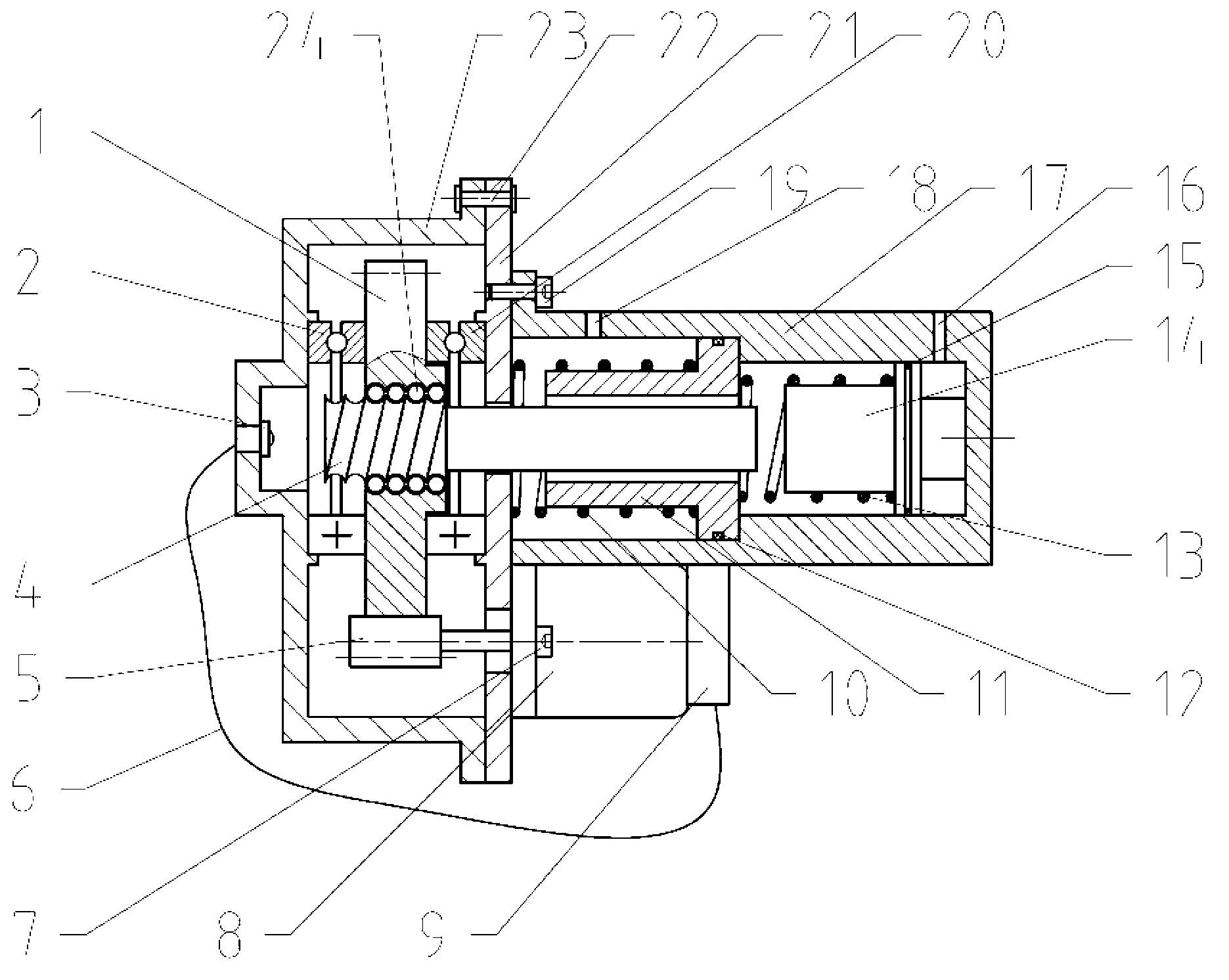
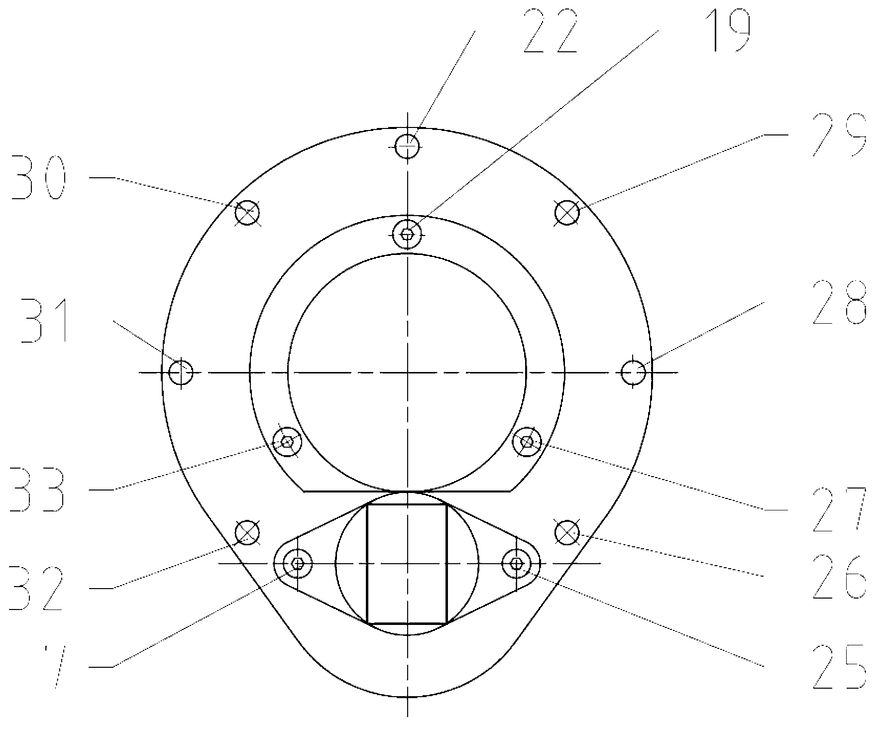
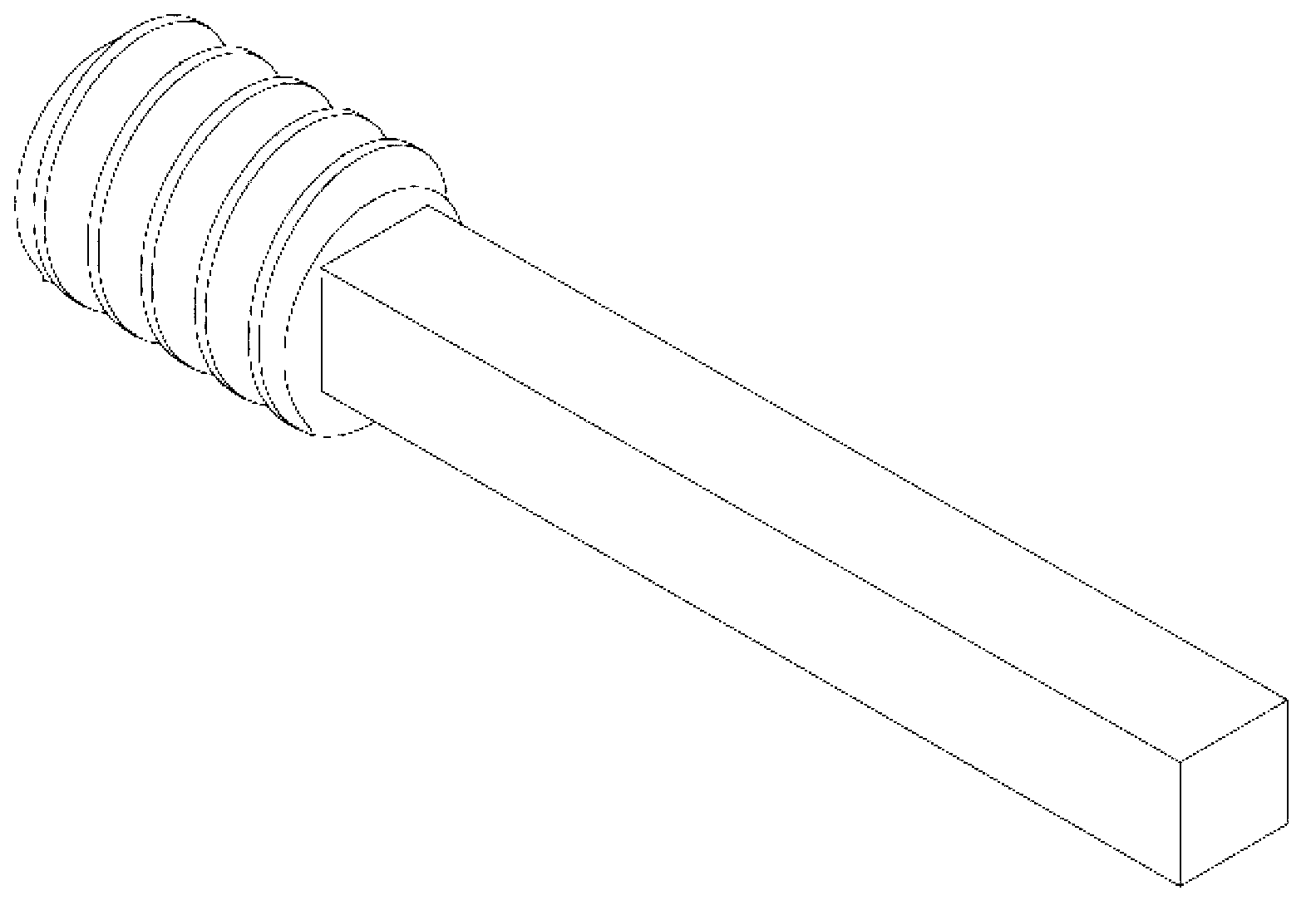
[0041] refer to figure 1 and figure 2 , the active brake pedal stroke simulator of the present invention comprises a toothed internal circulation nut 1, a first thrust bearing 2, a limit switch 3, a screw mandrel 4, a driving gear 5, a limit switch signal line 6, First motor fixing bolt 7, motor 8, motor controller 9, second piston spring 10, second piston 11, second piston sealing ring 12, first piston spring 13, first piston 14, first piston sealing ring 15 , the simulator cylinder 17, the second partition connecting bolt 19, the second thrust bearing 20, the partition 21, the fourth rear cover connecting rivet 22, the rear cover 23, the ball 24, the second motor fixing bolt 25, the seventh rear cover Cover connecting rivet 26, third partition connecting bolt 27, sixth rear cover connecting rivet 28, fifth rear cover connecting rivet 29, third rear cover connecting rivet ...


PUM


Abstract

The invention discloses an active brake pedal travel simulator and a control method of the active brake pedal travel simulator. The active brake pedal travel simulator and the control method of the active brake pedal travel simulator and aim to solve the problem that in the prior art, requirement for hydraulic adjusting unit performance is too high, and utilization of existing components is insufficient. The active brake pedal travel simulator comprises an inner circulation nut with teeth, a screw rod ejector rod, a driving gear, a motor, a second piston, a first piston, a simulator cylinder body, a spacing board, a limit switch and a rear cover, wherein the rear cover and the simulator cylinder body are arranged on the left side and the right side of the spacing board, the inner circulation nut with the teeth is arranged on the rear cover and the spacing board through two thrust bearings, the left end of the screw rod ejector rod is arranged inside a hole of the inner circulation nut with the teeth and is in rolling connected with the inner circulation nut with the teeth, the right end of the screw rod ejector rod is inserted into the second piston inside the simulator body, the first piston is arranged on the right side of the piston, the motor is arranged on the lower portion of the simulator cylinder body, the motor and the driving gear are fixedly connected, a motor control device is arranged on the motor, the limit switch is arranged on the rear cover, and the limit switch and the motor control device are in wire connection. The invention further provides the control method of the active brake pedal travel simulator.

Description

technical field [0001] The invention relates to a simulation device applied in the field of automobile brake systems, more precisely, the invention relates to an active brake pedal stroke simulator and a control method thereof. Background technique [0002] In order to achieve the goal of reducing energy consumption and increasing driving range, new energy vehicles have introduced regenerative braking systems. At present, in order to obtain good braking performance and meet the requirements of relevant regulations, the existing regenerative braking system adopts the combination of traditional hydraulic (or pneumatic) braking and motor regenerative braking. [0003] In order to improve the energy recovery rate of the regenerative braking system, it is necessary to reasonably distribute and adjust the braking force of the motor and the hydraulic (or pneumatic) braking force. The brake pedal of the regenerative braking system still has a pedal feel close to that of a tradition...

Claims


Application Information

Patent Timeline
Patent Type & Authority Applications(China)
IPC IPC(8): B60T7/04B60T13/66
Inventor 初亮赵迪姚亮杨毅喻中朋张永生蔡健伟王兆伟武同波张世桐
Owner JILIN UNIV
Learn More