Electrical cabinet for numerically-controlled machine tool

A technology of CNC machine tools and electrical cabinets, applied to electrical components, substation/switch layout details, substation/distribution device shells, etc., can solve problems such as troublesome operation and inability to achieve adjustment, and achieve the effect of simple structure

Active Publication Date: 2014-10-29
UNIV OF JINAN
View PDF6 Cites 5 Cited by
  • Summary
  • Abstract
  • Description
  • Claims
  • Application Information

AI Technical Summary

Problems solved by technology

The traditional way of fixing the machine tool electrical cabinet is cumbersome to operate, and at the same time, the partition is fixed after installation and cannot be adjusted conveniently

Method used


Image

  • Electrical cabinet for numerically-controlled machine tool
  • Electrical cabinet for numerically-controlled machine tool

Examples


Embodiment 1

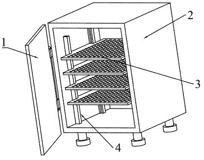
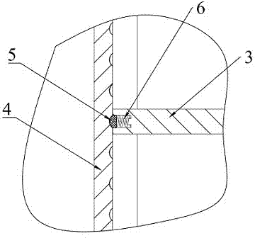
[0016] like figure 1 , figure 2 As shown, the electrical cabinet for CNC machine tools has a structure including: cabinet door 1, cabinet body 2, partition plate 3, guide groove 4, positioning block 5, and spring 6; two guide grooves 4 are vertically arranged on the inner side of the cabinet body 2, The inner side of the guide groove 4 is evenly provided with hemispherical positioning holes along the length direction. There are extending parts in the middle of the left and right sides of the partition plate 3. The extending parts are stuck between the two guiding grooves 4. There are blind holes on both sides of the extending part. There is a protrusion at the center of the inner end surface of the blind hole, the diameter of the protrusion is smaller than the inner diameter of the spring 6, one end of the spring 6 is placed on the protrusion, and the other end of the spring 6 is in contact with the end surface of the positioning block 5, and the positioning block 5 is as a w...

Embodiment 2

[0021] The electrical cabinet for numerically controlled machine tools described in this embodiment, when in use, inserts the spring 6 into the blind holes at both ends of the protruding part on both sides of the partition 3, presses the positioning block 5 on the end face of the spring 6, and at this time the partition 3 The protruding parts on both sides are stuck between the guide grooves 4 on the inner side of the cabinet body 2, adjust the vertical position of the partition 3 up and down, and use the cooperation between the positioning block 5 and the positioning hole to fix the partition 3 and then use it .


PUM


Abstract

The invention provides an electrical cabinet for a numerically-controlled machine tool and belongs to the field of the numerically-controlled machine tool accessories. The electrical cabinet structurally comprises a cabinet door, a cabinet door, a separator, guide grooves, positioning blocks and springs; two guide grooves are vertically formed in the internal side surface of the cabinet body, hemispherical positioning holes are evenly formed at the inner sides of the guide grooves in the length direction, extension parts are formed in the middle parts of the left and right sides of the separator and clamped between the two guide grooves, blind holes are formed at both sides of the extension parts, projections are formed in the central positions of the inner end faces of the blind holes, the diameter of the projection is smaller than the diameter of the inner hole of the spring, one end of each spring sleeves the corresponding projection, while the other end of the spring is in contact with an end face of the corresponding positioning block, each positioning block is entirely cylindrical and one end of the positioning block is a hemispherical projection, and the hemispherical end of the positioning block is located in the corresponding hemispherical positioning hole at the inner side of the corresponding guide groove. The electrical cabinet for the numerically-controlled machine tool is simple in structure, and capable of realizing slippage of a supporting plate.

Description

technical field [0001] The invention relates to an electric cabinet for a numerically controlled machine tool, belonging to the field of numerically controlled machine tool accessories. Background technique [0002] Machine tool electrical cabinets are currently necessary accessories in CNC machine tools, mainly to accommodate various electronic components and provide support for electronic components. The traditional way of fixing the electrical cabinet of the machine tool is cumbersome to operate, and at the same time, the partition is fixed after installation and cannot be adjusted conveniently. Contents of the invention [0003] In view of the above problems, the present invention provides an electrical cabinet for a numerical control machine tool, which has a simple structure and can realize the sliding of the support plate. [0004] The technical scheme that the present invention takes is: [0005] The electrical cabinet for CNC machine tools, its structure includ...

Claims


Application Information

Patent Timeline
Patent Type & Authority Applications(China)
IPC IPC(8): H02B1/30H02B1/052
Inventor 鲁帅帅昃向博田田张孟杰栾富钰
Owner UNIV OF JINAN
Why Eureka
Try Eureka