Rotary electric machine and driving apparatus using the same

A technology for rotating motors and rotating shafts, applied in the field of driving devices, which can solve the problems of difficulty in forming the bottom part and increasing costs

Active Publication Date: 2014-10-29
DENSO CORP
View PDF7 Cites 13 Cited by
  • Summary
  • Abstract
  • Description
  • Claims
  • Application Information

AI Technical Summary

Problems solved by technology

However, it is difficult to form the bottom part

Method used


Image

  • Rotary electric machine and driving apparatus using the same
  • Rotary electric machine and driving apparatus using the same
  • Rotary electric machine and driving apparatus using the same

Examples


Embodiment )

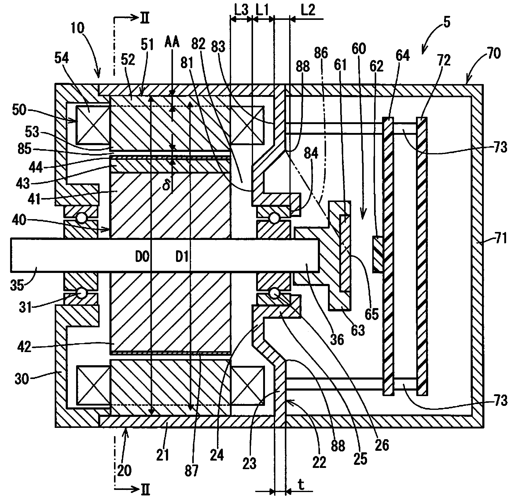
[0019] figure 1 A drive device 5 applied to a motor 10 corresponding to a rotary electric machine according to an embodiment of the present disclosure is shown. The drive device 5 is used as a power source of a power steering system of a vehicle.

[0020] First, refer to figure 1 and figure 2 , the configuration of the driving device 5 will be described. The drive device 5 is a mechanically and electrically integrated type drive device integrally equipped with a motor 10 and a control device 70 for controlling the motor 10 .

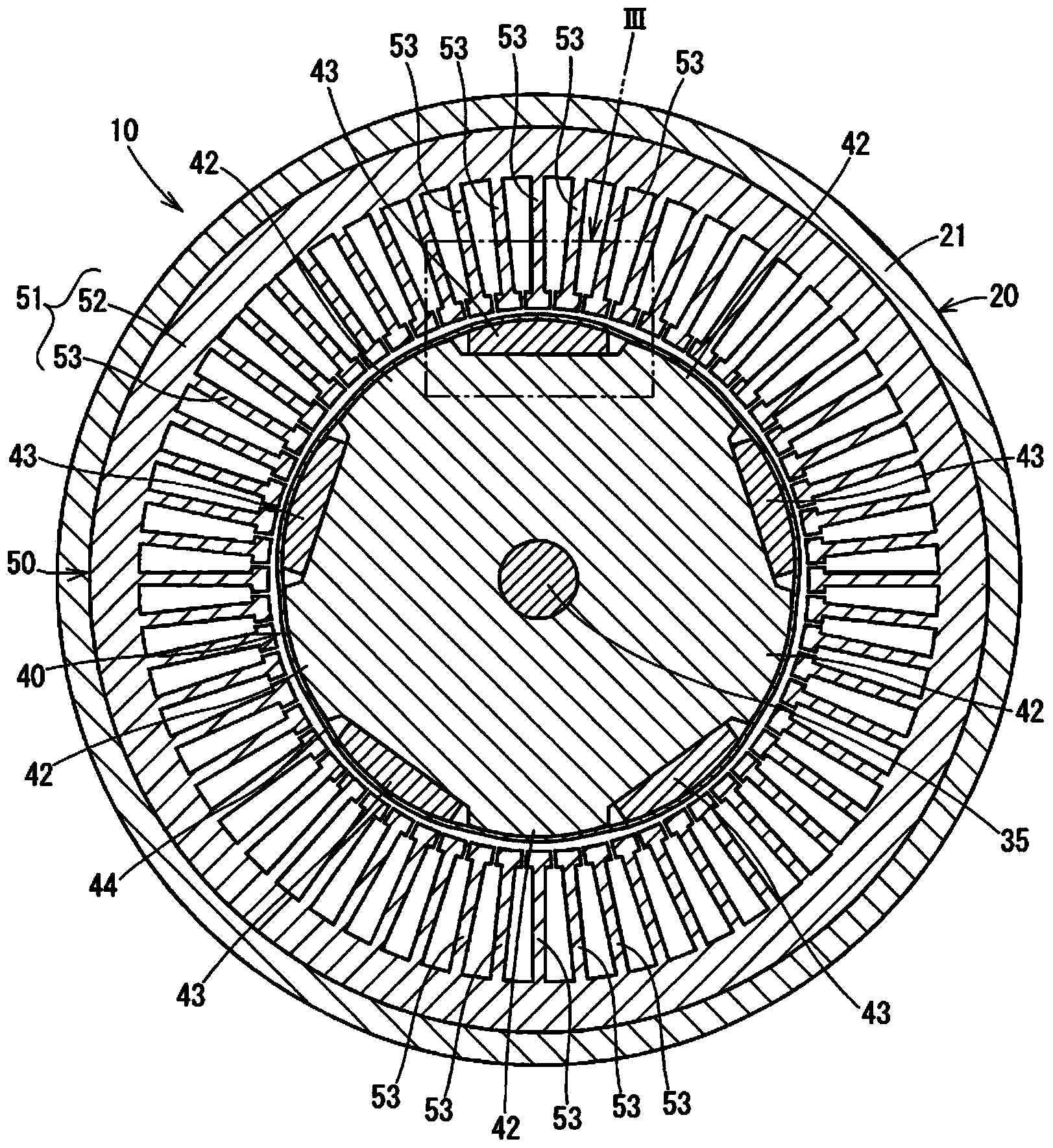
[0021] The motor 10 is a brushless motor having three phases, and includes a case 20 , a first cover 30 , a first bearing 26 , a second bearing 31 , a rotating shaft 35 , a rotor 40 , a stator 50 and a position detection portion 60 .

[0022] The case 20 is a stamped product of a plate member made of soft magnetic material, and includes a cylindrical portion 21 and a bottom portion 22 blocking a first end of the cylindrical portion 21 . The cylindr...


PUM


Abstract

A motor includes a stator core fitted to a cylindrical portion of a case, a rotor core being rotatable in the stator core, soft magnetic poles radially extending from the rotor core, and magnet poles disposed between the soft magnetic poles. The case includes a bottom portion having a ring-shaped plate portion, a protrusion portion, and a bearing-supporting portion extending from the protrusion portion. A condition that L2≧t and a condition that L1≧L2 are met, wherein t represents a thickness of the bottom portion, L1 represents a distance in an axial direction between a side surface of the ring-shaped plate portion close to the stator core and a protrusion end of the protrusion portion close to the rotor core, and L2 represents a distance in the axial direction between the side surface and an end surface of a bearing opposite to the rotor core.

Description

technical field [0001] The present disclosure relates to a rotating electric machine and a driving device using the same. Background technique [0002] JP-2012-005252A (US2011 / 0309707A1) discloses an alternating pole type motor in which half of the magnetic poles are soft magnetic poles, thereby reducing a large amount of rare earth elements. In this case, the rare earth element corresponds to the material of the permanent magnet included in the rotor used as the magnetic field of the permanent magnet. The rotor core and the stator core form a main magnetic circuit for generating torque. It is well known that the magnetic flux generated by the permanent magnets of the rotor is prone to leakage from the main magnetic circuit. According to JP-2012-005252A, the gap distance between the central part of the bottom part of the bottomed cylindrical casing in the axial direction and the rotor core is at least equal to and at most ten times the gap distance between the stator core ...

Claims


Application Information

Patent Timeline
IPC IPC(8): H02K11/00H02K5/04H02K5/16H02K29/08
CPCH02K11/0073H02K5/04H02K11/0021H02K29/03H02K29/08H02K2201/03H02K2213/03H02K1/2746H02K11/21H02K11/215H02K5/15H02K29/06
Inventor 谷口真
Owner DENSO CORP
Why Eureka
Try Eureka