Injection mould with pushing needle for pushing out

A technology for injection molds and thimbles, which is applied in the field of injection molds where thimbles are ejected, and can solve problems such as poor pulling force and inconvenient setting of plastic parts

Inactive Publication Date: 2014-11-05
上海伟阳纸业有限公司
View PDF1 Cites 7 Cited by
  • Summary
  • Abstract
  • Description
  • Claims
  • Application Information

AI Technical Summary

Problems solved by technology

The injection mold has poor pulling strength, and it is

Method used


Image

  • Injection mould with pushing needle for pushing out

Examples


Example Embodiment

[0017] In order to make the technical means, creative features, goals and effects achieved by the present invention easy to understand, the present invention will be further described below in conjunction with specific embodiments.

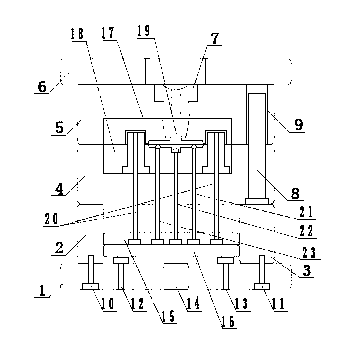
[0018] like figure 1 As shown, an injection mold for ejector pin ejection includes a base plate 1, a rear template 4 and a panel 6, the base plate 1 is provided with a top stick hole 14, and the base plate 1 is provided with a first backing plate 2 and a second backing plate 3, The rear formwork 4 is arranged on the first backing plate 2 and the second backing plate 3, and the front formwork 5 is arranged on the panel 6, and the front formwork 5 and the back formwork 4 are movably connected by guide pillars 8; the guide pillars 8 are arranged in the back formwork 4 , and pass through the front template 5, the rear template 4 is provided with a rear mold insert 18, the front template 5 is provided with a front mold insert 17, and a flow channel 19 ...


PUM


Abstract

The invention discloses an injection mould with a pushing needle for pushing out. The injection mould includes a bottom plate, a back mould plate and a surface plate. The surface plate is provided with a front mould plate. The front mould plate and the back mould plate are movably connected to each other through a guide column. A back mould insert is arranged in the back mould plate and a front mould insert is arranged in the front mould plate. A flow pass is disposed between the front mould insert and the back mould insert. The bottom plate is provided with a pushing needle bottom plate. The pushing needle bottom plate is provided with the pushing needle, a first water opening pushing needle, a second water opening pushing needle and a third water opening pushing needle, wherein heads of the pushing needle, the first water opening pushing needle, the second water opening pushing needle and the third water opening pushing needle are disposed in the flow pass. The head of the second water opening pushing needle is fan-shaped and the heads of the first water opening pushing needle and the third water opening pushing needle are ball-shaped. The injection mould is simple in structure and is convenient to use. A material is convenient to push out. The injection mould is large in material-pushing strength and a plastic workpiece can be pushed out more conveniently during a demoulding process.

Description

technical field [0001] The invention relates to an injection mold, in particular to an injection mold with ejector pins. Background technique [0002] In the prior art, for example, patent ZL201120548492.X discloses an injection mold, which includes a movable mold fixed plate, a fixed mold fixed plate, a movable mold foot, and a fixed mold foot, and is characterized in that it also includes: a movable mold plate, a fixed mold plate, a core , Injection runner, thimble plate, thimble, a fixed template is set under the foot of the fixed mold, a movable template is set above the movable mold foot, a mold core is set on the movable template, and an injection runner is opened on the fixed plate of the fixed mold The injection port, the injection runner is connected with the mold core, a thimble plate is arranged under the fixed plate of the fixed mold, and a thimble is arranged under the thimble plate, and the thimble passes through the fixed plate and is located above the mold co...

Claims


Application Information

Patent Timeline
IPC IPC(8): B29C45/26B29C45/40
CPCB29C45/401B29C2045/334B29C2045/4084B29C2045/4094
Inventor 程齐
Owner 上海伟阳纸业有限公司
Why Eureka
Try Eureka