
Fingerprint identification detection component and its electronic device

A technology for fingerprint recognition and detection components, applied in character and pattern recognition, computer parts, instruments, etc., can solve the problems of poor final imaging effect of fingerprints, difficult to meet the needs of thin portable terminals, long distance, etc., so as to reduce the distance , Improve the final imaging effect, reduce the effect of the overall thickness

Active Publication Date: 2018-01-30
NANCHANG OUFEI BIOLOGICAL IDENTIFICATION TECH
View PDF6 Cites 0 Cited by
  • Summary
  • Abstract
  • Description
  • Claims
  • Application Information

AI Technical Summary

Problems solved by technology

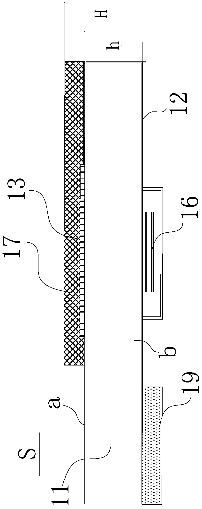
[0004] The thickness H of this portable terminal with fingerprint identification and detection components has increased compared with the thickness h of the original cover plate 11, and it is difficult to meet the thinning requirements of modern portable terminals.
[0005] In addition, for another portable terminal with a fingerprint identification and detection component, it arranges the fingerprint detection element and the fingerprint identification chip under the cover, so that the distance between the user's finger and the fingerprint detection element is relatively long, so that the fingerprint of the user's finger The final imaging effect is poor
The thickness of this portable terminal with fingerprint identification and detection components has also increased compared with the thickness of the original cover plate. Similarly, it is difficult to meet the thinning requirements of modern portable terminals.

Method used


Image

  • Fingerprint identification detection component and its electronic device
  • Fingerprint identification detection component and its electronic device
  • Fingerprint identification detection component and its electronic device

Examples


Embodiment 1

[0063] see Figure 3A and Figure 3B As shown, the fingerprint identification and detection assembly of the first embodiment of the present invention includes a cover plate 21 , a fingerprint sensor module and a printed circuit board 29 .

[0064] The cover plate 21 has a first surface a and a second surface b corresponding to the first surface. The second surface b is provided with a groove c. The cover plate 21 may be a cover plate made of strengthened glass, tempered glass, polycarbonate, polycarbonate, ceramic or sapphire. The cover plate 21 is preferably made of high-strength material to effectively protect the lower components. The fingerprint sensor module includes a fingerprint detection element 23 . The fingerprint detection element 23 is accommodated in the groove c of the cover plate 21 . The printed circuit board 29 is electrically connected to the fingerprint detection element 23 . The printed circuit board 29 is located on the second surface b of the cover ...

Embodiment 2

[0068] see Figure 3A and Figure 4 As shown, the fingerprint identification and detection assembly of the second embodiment of the present invention includes a cover plate 21 , a fingerprint sensing module, a color layer 25 , an encapsulant 28 and a printed circuit board 29 .

[0069] Like the cover plate 21 of the first embodiment, the cover plate 21 has a first surface a and a second surface b corresponding to the first surface. The second surface b is provided with a groove c.

[0070] The color layer 25 is located at the bottom c1 of the groove c for color decoration. The color layer 25 includes an ink layer. The ink layer can be a black ink layer, a gray ink layer, a white ink layer or other color ink layers. In some embodiments, color layer 25 may include multiple layers of ink. For example, the color layer 25 includes a black ink layer and a white ink layer. For another example, the color layer 25 includes multiple ink layers with the same color. Specifically, t...

Embodiment 3

[0076] see Figure 5 As shown, the fingerprint identification and detection assembly of the third embodiment of the present invention includes a cover plate 21 , a fingerprint sensor module, a color layer 25 , an encapsulant 28 and a printed circuit board 29 . Its structure is substantially the same as that of the second embodiment, the only difference being that a flexible circuit board 203 is provided on the side of the printed circuit board 29 away from the fingerprint sensing module. The flexible circuit board 203 is preferably electrically connected to the printed circuit board 29 through solder paste. In this embodiment, the printed circuit board 29 conducts electricity on both sides.


PUM


Abstract

The invention discloses a fingerprint identification and detection assembly and an electronic device of the fingerprint identification and detection assembly. The fingerprint identification and detection assembly comprises a cover plate and a fingerprint sensing module, the cover plate is provided with a first face and a second face opposite to the first face, and a groove is formed in the second face of the cover plate; the fingerprint sensing module is located in the groove of the cover plate, and fingerprints which correspond to an induction area of the fingerprint sensing module and are operated on the first face of the cover plate are identified and detected through the fingerprint sensing module. The fingerprint sensing module comprises a fingerprint detection element and a fingerprint identification chip, the fingerprint detection element is located at the bottom of the groove of the cover plate, the fingerprint identification chip is electrically connected with the fingerprint detection element, and the fingerprint detection element is located between the bottom of the groove of the cover plate and the fingerprint identification chip. By means of the fingerprint identification and detection assembly and the electronic device, the groove is formed in the cover plate and used for containing the fingerprint sensing module, the overall thickness of the cover plate and the fingerprint sensing module is reduced, thinning of electronic devices such as portable terminals is facilitated, and the fingerprint identification and detection assembly and the electronic device are particularly suitable for mobile phones without solid HOME keys.

Description

technical field [0001] The invention relates to the field of fingerprint identification, in particular to a fingerprint identification detection component and an electronic device with the fingerprint identification detection component. Background technique [0002] With the wide application of portable terminals in people's daily life, the functions of the current portable terminals are becoming more and more powerful, and such diversified functions are convenient for users. However, while the portable terminal provides more convenience for the user, it carries too much private information. If the portable terminal is lost or stolen, the information is easily leaked because there is no relevant protection. cause inconvenience to users. Therefore, it is very necessary to do some security settings on the portable terminal. In addition, compared with keypad locks and passwords, it is more confidential and convenient to use fingerprint recognition to keep secret. [0003] A ...

Claims


Application Information

Patent Timeline
Patent Type & Authority Patents(China)
IPC IPC(8): G06K9/00
Inventor 唐根初刘伟蒋芳
Owner NANCHANG OUFEI BIOLOGICAL IDENTIFICATION TECH
Learn More