Cell pack, device and method for manufacturing cell pack

A technology for manufacturing devices and battery packs, which is applied to battery pack components, battery covers/end covers, circuits, etc., and can solve problems such as increased manufacturing costs

Active Publication Date: 2014-11-05
PANASONIC ENERGY CO LTD MORIGUCHI SHI
View PDF5 Cites 8 Cited by
  • Summary
  • Abstract
  • Description
  • Claims
  • Application Information

AI Technical Summary

Problems solved by technology

However, in this case, the case needs to be designed separately, and a dedicated mold for molding each case is required, and there is a problem that the manufacturing cost increases.

Method used


Image

  • Cell pack, device and method for manufacturing cell pack
  • Cell pack, device and method for manufacturing cell pack
  • Cell pack, device and method for manufacturing cell pack

Examples


Embodiment 1

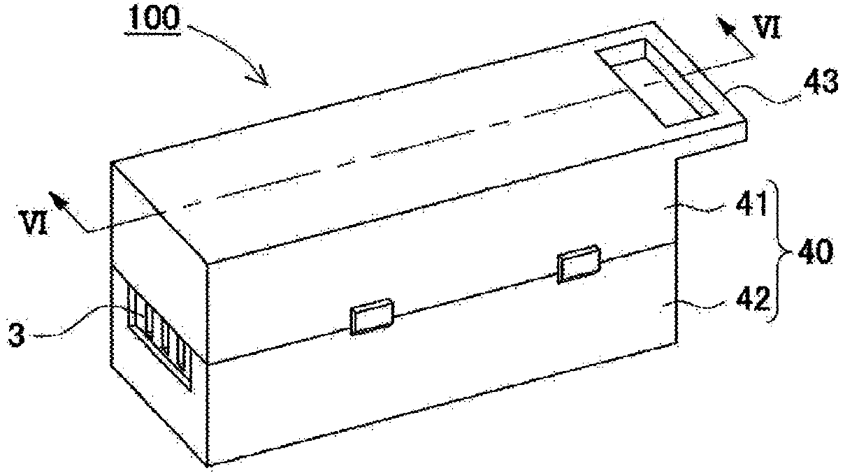
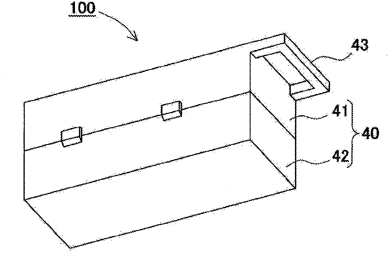
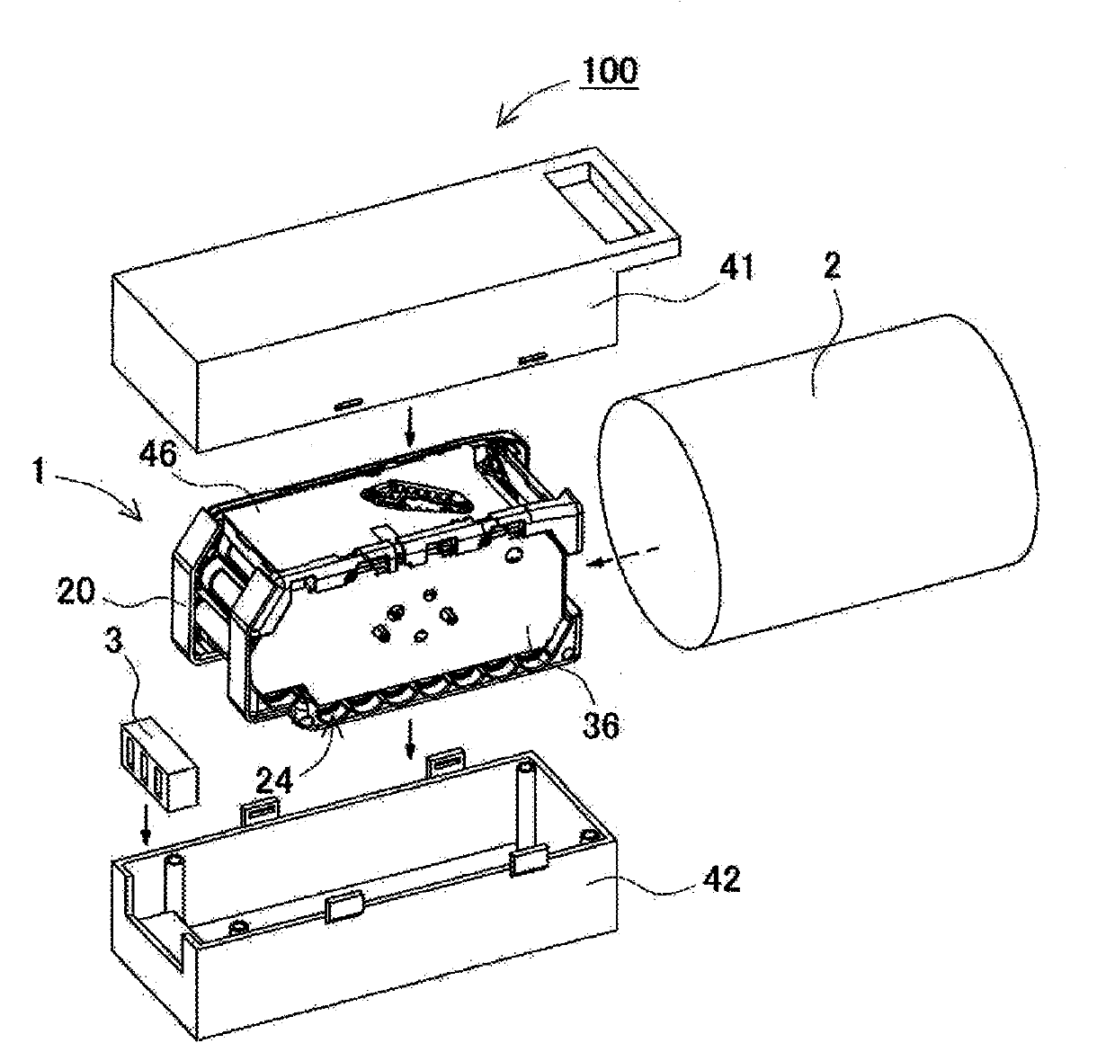
[0079] Figure 1 to Figure 5 An example of application to a battery pack for an assist bicycle is shown as the battery pack 100 according to Embodiment 1 of the present invention. These figures represent the following, respectively: figure 1 is a perspective view showing the appearance of the battery pack 100 of the first embodiment; figure 2 Viewed obliquely from the rear side figure 1 A perspective view of the appearance of the battery pack 100; image 3 yes figure 1 An exploded perspective view of the battery pack 100; Figure 4 It is self image 3 The state of further decomposed the exploded perspective view of the state of the battery part 1; Figure 5 Viewed obliquely from the rear side Figure 4 The external perspective view and enlarged view of the battery pack 100; Figure 6 yes figure 1 Sectional view of VI-VI. The battery pack 100 shown in these figures is composed of a case 40 and a battery unit 1 housed inside. Such as Figure 1 ~ Figure 4 As show...

Embodiment 2

[0108] First, the battery pack 200 of Example 2 is shown in Figure 11 ~ Figure 12 . These figures represent the following, respectively: Figure 11 It is a cross-sectional view and a partially enlarged view of the battery pack 200 of Embodiment 2; Figure 12 is said to be Figure 11 An exploded cross-sectional view of a state in which the lower case 42B is separated from the battery unit 1B. The external appearance of the battery pack 200 is the same as that of the first embodiment, but the internal battery components are different. Specifically, battery unit 1B in Example 2 uses a total of 40 battery cells 10 connected in series×4 in parallel. In this second embodiment, the case-side protrusion 28B of the battery case 20B and the case-side rib 48B of the lower case 42B are offset so as to be located at positions not to interfere with each other when the battery part 1B is inserted into the lower case 42B. . Thus, it is possible to Figure 11 , Figure 12 As shown, th...


PUM


Abstract

To make it possible to avoid mix-ups of cell holders housed in outer cases so that cell packs can be assembled correctly. An outer case (40) is provided with a case-side rib (48) protruding from the first position on the inner surface, and the cell holder (20) is provided with a holder-side projection (28) protruding from the second position on the outer surface. The cell holder (20) is configured so that the second position, at which the holder-side projection (28) is provided, is located at a different position to that for a cell holder (20B) of a different type. The first and second positions are disposed at a position at which the case-side rib (48) does not interfere with the holder-side projection (28) when the cell holder (20) is inserted into the outer case (40), and the case-side rib (48) interferes with the holder-side projection (28) when an attempt is made to insert the cell holder (20B) of a different type into the outer case (40). The first and second positions are disposed in symmetric positions centered on a predetermined axis of symmetry.

Description

technical field [0001] The present invention relates to a battery pack containing a plurality of battery cells and a manufacturing device and method of the battery pack. Background technique [0002] A battery pack using multiple battery cells is used as a power source for assist bicycles, power tools, etc. In the battery pack, a plurality of battery cells are inserted into the casing while being fixed to the battery case. The battery box is provided with an accommodating space for accommodating the battery unit. In the case of using a cylindrical battery cell, the battery case fixes the holding tubes such that the cylindrical holding tubes accommodating the battery cells individually are in a parallel posture. [0003] In a battery pack, the output current can be changed by the number of battery cells connected in parallel, and the output voltage can be changed by the number of battery cells connected in series (for example, Patent Documents 1 and 2). For such a battery ...

Claims


Application Information

Patent Timeline
Patent Type & Authority Applications(China)
IPC IPC(8): H01M2/10B29C45/26H01M50/213H01M50/244H01M50/264H01M50/271H01M50/284
CPCB29C45/2673H01M2/34H01M2/1077H01M50/271H01M50/244H01M50/284H01M50/264H01M50/213Y02E60/10
Inventor 米田晴彦山上定男拜野真己神足昌人
Owner PANASONIC ENERGY CO LTD MORIGUCHI SHI
Why Eureka
Try Eureka