Optical cable splice box

A technology of optical cable transfer box and box body, which is applied in the direction of fiber mechanical structure, etc., can solve problems such as rainwater leakage equipment, burnout, safety accidents, etc., to eliminate trouble and untimely, good support effect, and good sealing Effect

Active Publication Date: 2014-11-12
NINGBO LINGTONG TELECOM EQUIP
View PDF5 Cites 7 Cited by
  • Summary
  • Abstract
  • Description
  • Claims
  • Application Information

AI Technical Summary

Problems solved by technology

[0002] With the advancement of technology, the application of optical cable transfer boxes is becoming more and more extensive. Generally, optical cable transfer boxes are placed outdoors, and there are multiple cooling holes on the optical cable transfer boxes to dissipate the heat generated during the use of equipment. However, when it rains, rainwater is likely to leak into the equipment through these heat dissipation holes. After the equipment touches the water, it will burn out and cause a major safety accident.

Method used


Image

  • Optical cable splice box
  • Optical cable splice box
  • Optical cable splice box

Examples


Embodiment Construction

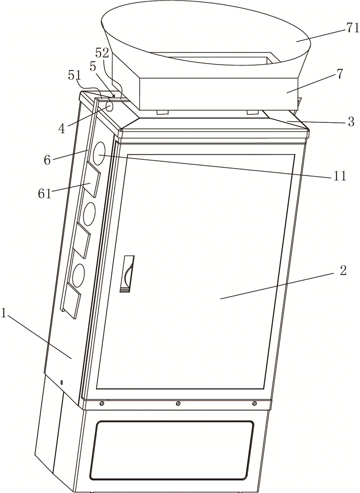
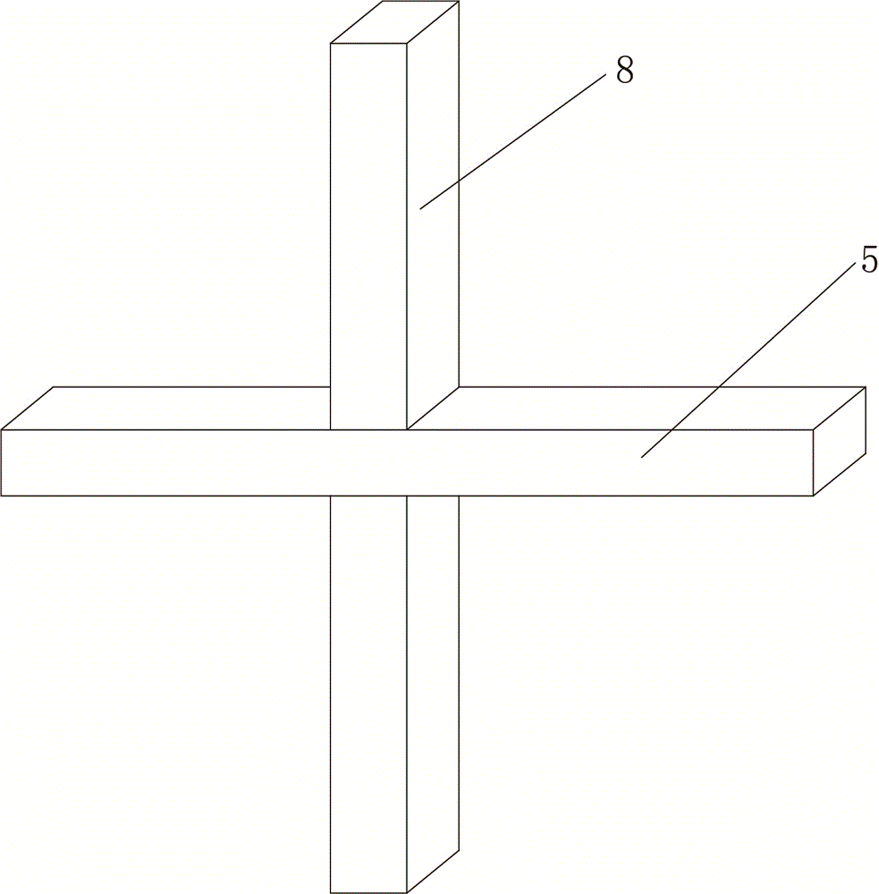
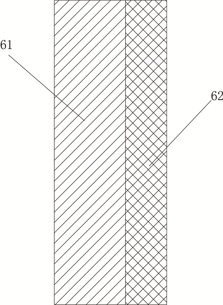
[0014] The present invention will be described in further detail below in conjunction with accompanying drawing and specific embodiment: see Figure 1-Figure 4 , the optical cable transfer box, including a box body 1, a box door 2 and a box cover 3, the box door 2 and the box cover 3 are installed on the box body 1, and several cooling holes are opened on the side of the box body 1 11. Two fulcrums 4 are arranged on the side of the box cover 3, and the two fulcrums 4 are respectively located on both sides of the box cover 3. All the fulcrums 4 are hinged with a lever 5, and the two ends of the lever 5 can shake up and down And lever 5 can not drop from fulcrum 4, and described lever 5 comprises No. 1 lever part 51 and No. 2 lever part 52, and if No. 2 lever part 52 length is longer, only need have a small amount of in water collection container 7. For rainwater, according to the lever theorem, the water collecting container can press down the No. 2 lever part 52, thereby seali...


PUM


Abstract

The invention relates to an optical cable splice box. The optical cable splice box comprises a box body, a box door and a box cover, the box door and the box cover are installed on the box body, the side faces of the box body are provided with a plurality of cooling holes, the side edges of the box cover are provided with two supporting points, levers are hinged to the supporting points, each lever comprises a first lever portion and a second lever portion, the end portion of each first lever portion is connected with a connection rod, the side face of each connection rod is vertically provided with a plurality of baffles capable of sealing the corresponding cooling holes, a water collection container is arranged on the upper portions of the second lever portions, and the levers are in the horizontal state when no object exists in the water collection container. In rainy days, the cooling holes can be sealed automatically, trouble and untimeliness of manual operation are eliminated, and therefore rainwater is prevented from entering the optical cable splice box.

Description

technical field [0001] The invention relates to an optical cable transfer box. Background technique [0002] With the advancement of technology, the application of optical cable transfer boxes is becoming more and more extensive. Generally, optical cable transfer boxes are placed outdoors, and there are multiple cooling holes on the optical cable transfer boxes to dissipate the heat generated during the use of equipment. However, when it rains, rainwater is likely to leak onto the equipment through these heat dissipation holes. After the equipment touches the water, it will burn out and cause a major safety accident. Contents of the invention [0003] Aiming at the deficiencies of the prior art, the present invention provides an optical cable transfer box, which can automatically seal the heat dissipation holes in rainy days, eliminating the trouble and delay of manual operation, thereby preventing rainwater from entering the optical cable transfer box. [0004] In order ...

Claims


Application Information

Patent Timeline
Patent Type & Authority Applications(China)
IPC IPC(8): G02B6/44
Inventor 邓奕丁高文雄林辉宣沈金标
Owner NINGBO LINGTONG TELECOM EQUIP
Why Eureka
Try Eureka