A Punch Position Adjustment Mechanism in Continuous Drawing Die

A technology for deep drawing dies and adjustment mechanisms, applied in the field of stamping dies, can solve the problems of increasing the cost of grinding punches and processing gaskets, time-consuming and laborious installation and debugging, and inability to directly adjust the height, so as to achieve simple structure and fast adjustment speed. , Adjust the effect of less time-consuming

Active Publication Date: 2016-05-11
松渤电器(上海)有限公司
View PDF7 Cites 0 Cited by
  • Summary
  • Abstract
  • Description
  • Claims
  • Application Information

AI Technical Summary

Problems solved by technology

The height of the punch of the drawing die and the punch of the shaping die cannot be adjusted directly. The drawing height can only be adjusted by grinding the corresponding punch or the corresponding gasket on the pad. To remove the entire mold first
Such an adjustment method not only increases the cost of grinding the punch and processing the gasket, but also takes time and effort in the installation and debugging process, which reduces the processing efficiency.

Method used


Image

  • A Punch Position Adjustment Mechanism in Continuous Drawing Die
  • A Punch Position Adjustment Mechanism in Continuous Drawing Die
  • A Punch Position Adjustment Mechanism in Continuous Drawing Die

Examples


Embodiment 1

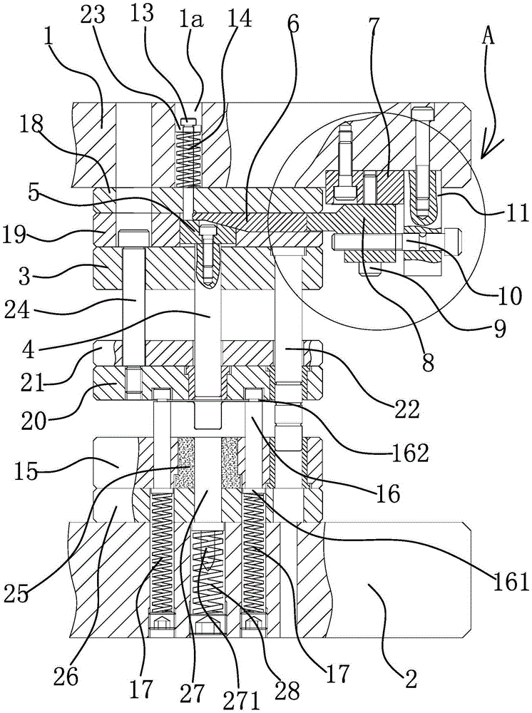
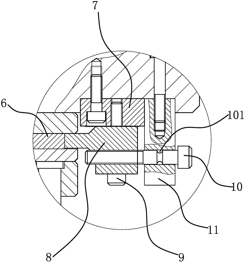
[0036] The continuous drawing die comprises an upper die base 1 and a lower die base 2, and a punch fixing plate 3 is fixed on the upper die base 1. Punch 4 is housed on the punch fixed plate 3, and punch 4 here can be drawing punch and shaping punch etc. The punch position adjustment mechanism in the continuous drawing die is arranged on the upper die base 1, including punch slide block 5, adjustment slide block 6, adjustment assembly and locking assembly.

[0037] Specifically, as figure 1 As shown, the punch fixing plate 3 is installed on the upper die base 1, and an upper backing plate 18 and a lining plate 19 are also installed between the punch fixing plate 3 and the upper die base 1, and the punch fixing plate 3 and the upper backing plate 18 And lining plate 19 is positioned on the upper mold base 1 by positioning pin, and is fastened by screw, and small guide post 22 is also installed on the punch fixed plate 3. There is a chute 1 on the liner 19, the punch slider 5...

Embodiment 2

[0043] The technical solution in this embodiment is basically the same as the technical solution in Embodiment 1, the difference is that in this embodiment, the adjustment assembly includes a sliding block, the sliding block is slidably connected on the punch fixing plate 3, and the sliding block is connected with the adjustment The slide block 6 is fixedly connected, the slide block has several positioning holes, and the punch fixing plate 3 has positioning pins which can cooperate with the positioning holes respectively. When it is necessary to adjust the position of the punch 4, first pull out the positioning pin from the positioning hole, push the sliding block to slide relative to the punch fixing plate 3, and drive the adjustment slider 6 to approach or move away from the punch slider 5, so that the punch The mold 4 rises or falls; after the adjustment is completed, insert the positioning pin into another corresponding positioning hole, so that the sliding block is fixedl...

Embodiment 3

[0045] The technical solution in this embodiment is basically the same as the technical solution in Embodiment 1, the difference is that in this embodiment, the locking assembly includes at least one disc spring sleeved on the punch 4, the disc spring One end leans against the punch fixing plate 3 , and the other end leans against the punch slide 5 . The belleville springs are easy to install and the cost is low; and the number and elastic force of the belleville springs can be selected according to the required elastic force, which has little influence on the structure of the continuous drawing die itself.


PUM


Abstract

The invention provides a male die position adjusting mechanism in a continuous deep drawing die and belongs to the technical field of machinery. The problem that male die position adjusting in an existing continuous deep drawing die is not convenient is solved. The male die position mechanism in the continuous deep drawing die comprises a male die sliding block and an adjusting sliding block. The male die sliding block is fixed at the end, toward an upper die base, of a male die. A first oblique face is arranged on the upper surface of the male die sliding block. A second oblique face matched with the first oblique face is arranged at one end of the adjusting sliding block. The adjusting siding block abuts against the male die sliding block, so that the first oblique face and the second oblique face are attached. An adjusting component which can enable the adjusting sliding block to get close to or be far away from the male die sliding block is arranged at the other end of the adjusting sliding block. A locking component which enables the male die sliding block to tend to move to the adjusting sliding block is arranged on the male die sliding block. According to the adjusting mechanism, the position of the male die is adjusted through the adjusting component, consumed time in each-time adjusting is short, production efficiency is improved, and an adjusting operation process is safe and reliable.

Description

technical field [0001] The invention belongs to the technical field of stamping dies, and relates to a continuous drawing die, in particular to a punch position adjustment mechanism in the continuous drawing die. Background technique [0002] Cold stamping die is a kind of process equipment for processing sheet metal into parts in cold stamping process. Under room temperature conditions, the cold stamping die exerts a certain pressure on the sheet under the drive of the press to cause separation or plastic deformation, so as to obtain the required shape of the part. According to the nature of the process, cold stamping dies can be divided into blanking dies, bending dies, deep drawing dies, forming dies, multi-station progressive dies and riveting dies. [0003] The drawing die is used to make the sheet blank into an open hollow part or to further change the shape and size of the hollow part. For example, the Chinese patent [application number 201010133320.6; application pu...

Claims


Application Information

Patent Timeline
Patent Type & Authority Patents(China)
IPC IPC(8): B21D37/00B21D22/20
Inventor 金龙建
Owner 松渤电器(上海)有限公司
Why Eureka
Try Eureka