Rotary transfer scraper conveyor

A scraper conveyor and rotating mechanism technology, applied in the direction of conveyors, mechanical conveyors, conveyor objects, etc., can solve the problems that the scraper conveyor cannot guarantee the continuous conveying of materials, reduce the continuous operation efficiency, etc., and achieve convenient assembly and disassembly. Fast, simple structure, flexible and stable rotation effect

Active Publication Date: 2016-02-24
JIANGXI LANXIANG HEAVY IND
View PDF6 Cites 0 Cited by
  • Summary
  • Abstract
  • Description
  • Claims
  • Application Information

AI Technical Summary

Problems solved by technology

In the case of continuous curved tunnels, "ㄈ", "Z", "S" or "W" and other irregular conveying line conditions, the installation of the hopper is restricted, and it is impossible to ensure that the scraper conveyor can continuously convey materials, reducing the continuous work efficiency

Method used


Image

  • Rotary transfer scraper conveyor
  • Rotary transfer scraper conveyor
  • Rotary transfer scraper conveyor

Examples


Embodiment 1

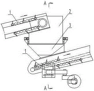
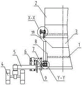
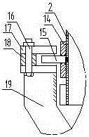
[0022] Example 1, in figure 1 , figure 2 , image 3 with Figure 4 Among them, the rotary transfer scraper conveyor includes a scraper conveyor body 1, a travel steering wheel arranged at the lower part of the front end of the scraper conveyor body, and a rotating device arranged between the front part of the conveyor body and the rear part of the conveyor, The walking steering wheel is movably connected with the two ends of the beam 9, and the walking steering wheel includes a universal wheel 4, a connecting rod 5 and a vertical shaft 6, and one end of the connecting rod is movably connected with the universal wheel, and the other end is connected to the cantilever through the rotating shaft. 7 are movably connected, and the cantilever is connected with one end of the beam. The rotating device is a cylinder rotating mechanism, and the cylinder rotating mechanism includes an upper cylinder 2, a lower cylinder 3 and a rotating sleeve connecting the upper cylinder and the lo...

Embodiment 2

[0023] Example 2, in Figure 5 , Image 6 , Figure 7 with Figure 8Among them, a rotary reloading scraper conveyor with a bogie structure includes a scraper conveyor body 1 and a walking steering wheel arranged at the lower part of the front end of the scraper conveyor body, and a scraper conveyor body and a scraper conveyor The rotating device between the rear parts of the conveyor, the walking universal wheels include universal wheels 4, the universal wheels are movably connected with the two ends of the crossbeam 9, and a blanking tray 2a is arranged at the rear of the scraper conveyor, and on the scraper The front part of the conveyor is provided with a beveled and annular receiving tray 3a. The rotating device is a bogie mechanism, and the bogie mechanism includes a joint, a load beam 5a and a rotary device. It is supported on both ends of the load-bearing beam, and the load-bearing beam is movably connected with the beam through a slewing device. The joint includes a...


PUM


Abstract

The invention discloses a rotary transferring scraper conveyer. The rotary transferring scraper conveyer comprises a scraper conveyer body (1), running steering wheels arranged at the ends of the scraper conveyer body, and a rotary mechanism arranged between the ends of the scraper conveyer body, wherein the rotary mechanism is of a barrel body mechanism or a steering frame mechanism, the barrel body mechanism comprises an upper barrel body (2), a lower barrel body (3) and a rotary sleeve connecting the upper barrel body and the lower barrel body, the steering frame mechanism comprises a loose joint, a bearing beam (5a) and a rotary device, a discharging disc (2a) is arranged on the rear portion of the conveyer, an annular receiving disc (3a) with an inclined opening is arranged on the front portion of the conveyer, and the loose joint comprises a supporting plate (11) arranged on a cross beam or the bearing beam, a rotary shaft (12) arranged on the supporting plate and a connecting plate (10) movably matched with the rotary shaft. The rotary transferring scraper conveyer can run in a servo mode and continuously turn around, achieves long-distance conveying, improves production efficiency greatly, reduces consumption of manpower, does not waste conveyed materials, and is beneficial to environment protection.

Description

technical field [0001] The invention relates to a scraper conveyor, in particular to a rotary and reloading scraper conveyor with a steering mechanism capable of rotating, reloading and walking. Background technique [0002] At present, in coal mines, non-coal mines, port terminals, freight yards and food processing industries, most of the scraper conveyors used are fixed, and multiple conveyors are also used to form a long-distance conveyor line by "lapping". And this kind of conveying line is completely "fixed type", and the said overlapping fixed type means that when it needs to be rotated after lapping, it must be disassembled manually, and cannot follow the rotation. , Manually follow up the installation or disassembly in time, and this disassembly work is frequent and wasteful, which affects the continuity of the transportation and seriously affects the transportation efficiency. [0003] To transport materials on the curve, it is also necessary to install a scraper c...

Claims


Application Information

Patent Timeline
Patent Type & Authority Patents(China)
IPC IPC(8): B65G47/52B65G37/00
Inventor 李杨陈振华李凯龚良发唐福新
Owner JIANGXI LANXIANG HEAVY IND
Why Eureka
Try Eureka