
Grinding jig for mobile phone parts

A technology of parts and jigs, which is applied in the field of grinding jigs, can solve the problems of low work efficiency of staff, and achieve the effects of stable and uniform adsorption force, time saving, and convenient pick and place

Pending Publication Date: 2018-04-03
KESEN SCI & TECH DONGTAI CO LTD
View PDF0 Cites 0 Cited by
  • Summary
  • Abstract
  • Description
  • Claims
  • Application Information

AI Technical Summary

Problems solved by technology

Undoubtedly, the above-mentioned work will consume a lot of time of the staff, resulting in low work efficiency of the staff

Method used


Image

  • Grinding jig for mobile phone parts
  • Grinding jig for mobile phone parts
  • Grinding jig for mobile phone parts

Examples


Embodiment 1

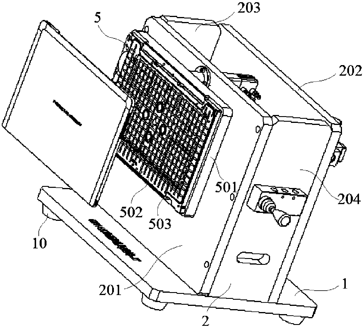
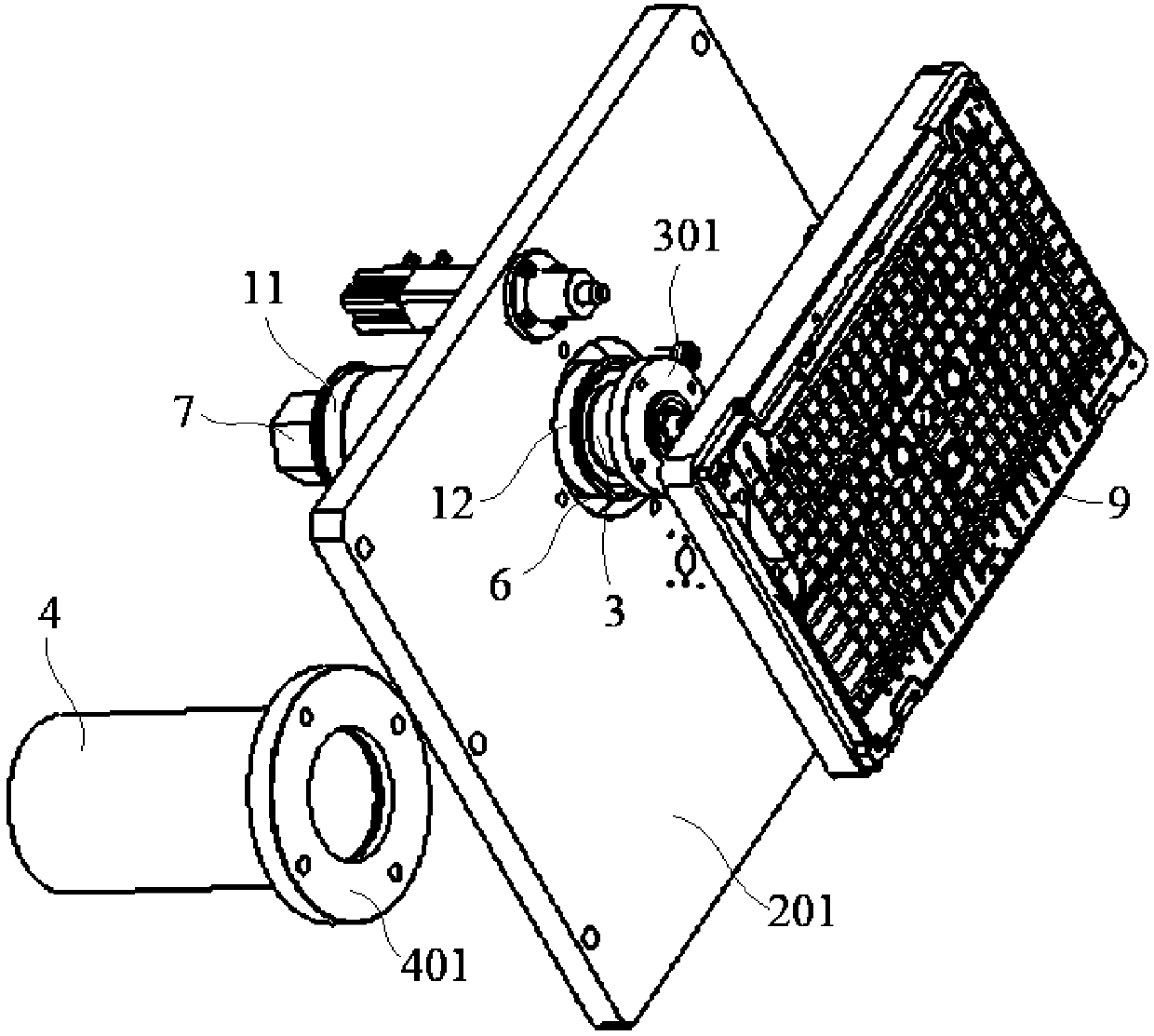
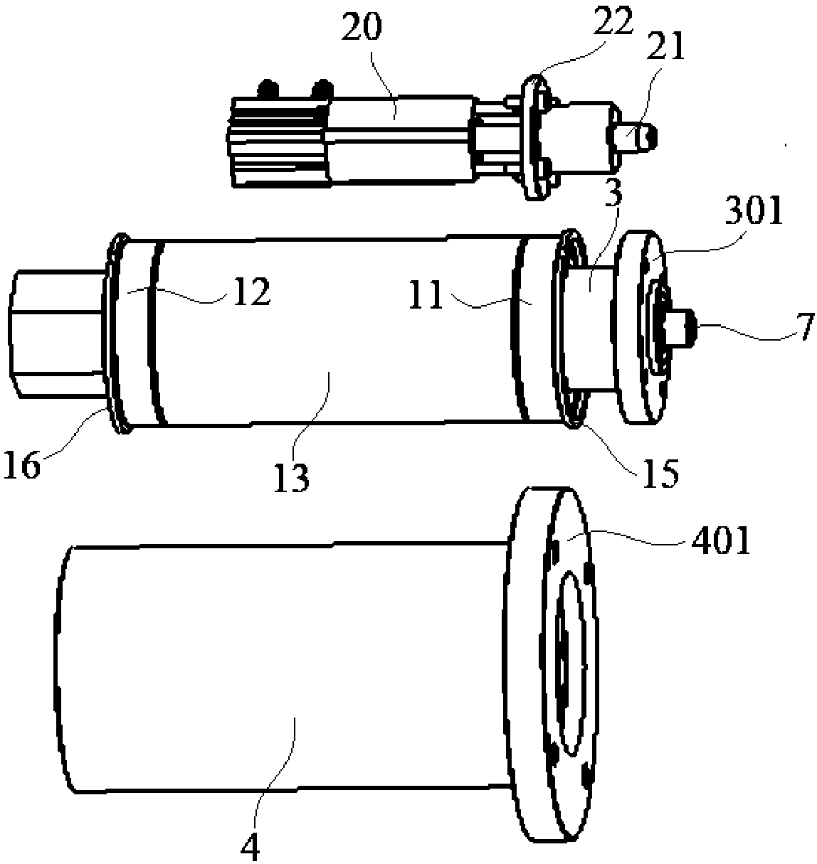
[0025] Embodiment 1: a kind of polishing jig for mobile phone parts, including base plate 1, support 2, main shaft 3, axle sleeve 4 and the fixing plate 5 for fixing product, described support 2 is fixed on the base plate 1, described The shaft sleeve 4 is fixedly connected with the bracket 2, and the main shaft 3 is embedded in the shaft sleeve 4 and connected with the fixed plate 5;

[0026] Described support 2 is made up of front side plate 201, rear side plate 202, left side plate 203 and right side plate 204, and described front side plate 201 and rear side plate 202 are arranged in parallel and on front side plate 201 and rear side plate 202 Both have a through hole 6 for the main shaft 3 to pass through. One end of the shaft sleeve 4 has a flange portion 401, and the other end of the shaft sleeve 4 passes through the through hole 6 of the front side plate 201 and the rear side plate 202 and passes through the protrusion. The edge portion 401 is fixedly connected to the ...

Embodiment 2

[0031] Embodiment 2: a kind of polishing tool for mobile phone parts, including base plate 1, support 2, main shaft 3, axle sleeve 4 and fixed plate 5 for fixing the product, described support 2 is fixed on the base plate 1, and described The shaft sleeve 4 is fixedly connected with the bracket 2, and the main shaft 3 is embedded in the shaft sleeve 4 and connected with the fixed plate 5;

[0032] Described support 2 is made up of front side plate 201, rear side plate 202, left side plate 203 and right side plate 204, and described front side plate 201 and rear side plate 202 are arranged in parallel and on front side plate 201 and rear side plate 202 Both have a through hole 6 for the main shaft 3 to pass through. One end of the shaft sleeve 4 has a flange portion 401, and the other end of the shaft sleeve 4 passes through the through hole 6 of the front side plate 201 and the rear side plate 202 and passes through the protrusion. The edge portion 401 is fixedly connected to ...


PUM


Abstract

The invention discloses a grinding jig for mobile phone parts. The grinding jig comprises a bottom plate, a bracket, a main shaft, a shaft sleeve and a fixing plate used for fixing a product. The support is fixed on the bottom plate, the shaft sleeve is fixedly connected with the support, the main shaft is embedded into the shaft sleeve and is connected with the fixing plate, and the other end ofthe shaft sleeve penetrates through through holes of the front side plate and the rear side plate and is fixedly connected with the front side plate through flange parts. A convex part is arranged atone end of the main shaft in the circumferential direction, and the convex part is fixedly connected with the fixing plate, inner grooves are formed in the inner side faces of the front end and the rear end of the shaft sleeve respectively, a plurality of locking air cylinders are further arranged, the locking air cylinders are fixedly connected with the support, piston rods of the locking air cylinders penetrate through the front side plate of the support and are connected with the fixing plate, and a plurality of circular grooves allowing the piston rods to be embedded are formed in the rearsurface of the connecting plate of the fixing plate. According to the grinding jig, good clamping and supporting for grinding operation of products is provided, workers can carry out grinding operation on products conveniently, and the working efficiency is improved.

Description

technical field [0001] The invention relates to a grinding fixture used for mobile phone parts, and relates to the field of high precision machining. Background technique [0002] At present, most of the appearance structural parts / accessories of mobile phones on the market are made of metal materials. The forming of metal materials mainly includes aluminum extrusion, die-casting, forging and other methods. No matter which forming method is used, it needs to be processed by CNC machining center after forming. There are poor appearance phenomena such as knife marks and scratches in the workpiece, and a series of appearance retreatments such as passivation, grinding and polishing, spraying, and anodizing are required for the workpiece. For the grinding of metal structural parts such as the middle frame of the mobile phone, the side of the protective case of the mobile phone, etc., in actual operation, the staff needs to hold each piece of poor-looking workpiece in turn for gri...

Claims


Application Information

Patent Timeline
Patent Type & Authority Applications(China)
IPC IPC(8): B24B9/04B24B41/06B24B47/14
CPCB24B9/04B24B41/06B24B47/14
Inventor 徐金根周华
Owner KESEN SCI & TECH DONGTAI CO LTD
Learn More