
A non-damping collision testing machine

A collision test and non-damping technology, which is applied in the field of mechanical engineering, can solve problems such as inconsistent collision conditions of objects, and achieve the effect of removing interference

Active Publication Date: 2017-04-12
SUZHOU VOCATIONAL UNIV
View PDF4 Cites 0 Cited by
  • Summary
  • Abstract
  • Description
  • Claims
  • Application Information

AI Technical Summary

Problems solved by technology

[0002] In recent years, in the process of R&D and production of many products, the research on reliability has been in-depth. As an important topic, the research on crash resistance has long been listed as the development direction of reliability. Various collision modes exist. There are big differences, but there is one thing in common: initial velocity and acceleration; in the past, there was a large fluid damping effect in the test equipment during the research process, but this part of the factor affected the analysis results of the test to a large extent, and the actual The collision condition of the object does not match; for this reason, a collision testing machine that can effectively remove the interference of the hydraulic oil on the return journey during the collision, so that the test results are more scientific and reliable

Method used


Image

  • A non-damping collision testing machine
  • A non-damping collision testing machine
  • A non-damping collision testing machine

Examples


Embodiment Construction

[0015] The present invention is described below in conjunction with accompanying drawing.

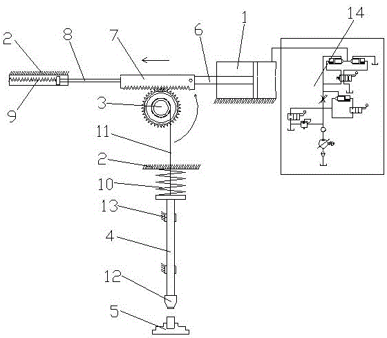
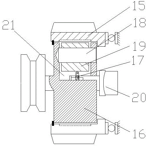
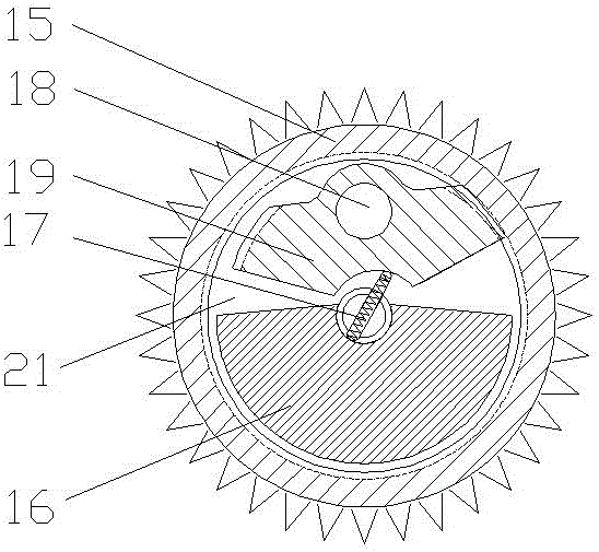
[0016] as attached Figure 1-4 Shown is a kind of non-damping impact testing machine according to the present invention, comprising a plunger cylinder 1, a bracket 2, a gear 3, a power storage spring 10, an impact push rod 4 and a fixture table 5; the plunger cylinder 1 A rack 7 is connected to the piston rod 6; the rack 7 is arranged above the gear 3 and meshed with the gear 3, and the gear 3 is driven to rotate by the movement of the rack 7; the gear 3 includes a gear housing 15 and a runner 16 The runner 16 is arranged in the gear housing 15 and can rotate in the gear housing 15; the runner 16 is provided with a groove 21; Tooth block 19; the bottom of the inner tooth block 19 is arranged in an arc; the central axis of the runner 16 is provided with a spring rod 17; one end of the spring rod 17 extends into the arc of the inner gear block 19 to control the runner 16 and the gear ho...


PUM


Abstract

The invention discloses an undamped impact testing machine. The undamped impact testing machine comprises a plunger type cylinder, a bracket, a gear, a power-saving spring, an impact push rod and a clamp table, wherein a rack is horizontally connected to the piston rod of the plunger type cylinder; the rack is arranged above and meshed with the gear; the gear comprises a gear housing and a runner; the runner is arranged in the gear housing and can rotate in the gear housing; a groove is formed in the runner; an internally-toothed block connected through a pin shaft is arranged in the groove; the bottom of the internally-toothed block is arc-shaped; a spring rod is arranged at the central axis of the runner; one end of the spring rod extends to the arc of the internally-toothed block to control the runner and the gear housing to move relatively or be fixed together; the spring rod is rotated by a shift lever; the tail end of the impact push rod is connected with the power-saving spring; the impact push rod is connected with the runner through a string; a heavy block is arranged at the top of the impact push rod; the clamp table is arranged right below the impact push rod. According to the invention, interference on the impact during returning of hydraulic oil in case of collision can be effectively removed, so that the test result is more scientific and reliable.

Description

technical field [0001] The invention relates to a non-damping collision testing machine, which belongs to the technical field of mechanical engineering. Background technique [0002] In recent years, in the process of R&D and production of many products, the research on reliability has been in-depth. As an important topic, the research on crash resistance has long been listed as the development direction of reliability. Various collision modes exist. There are big differences, but there is one thing in common: initial velocity and acceleration; in the past, there was a large fluid damping effect in the test equipment during the research process, but this part of the factor affected the analysis results of the test to a large extent, and the actual The collision condition of the object does not match; for this reason, a collision testing machine that can effectively remove the interference of the hydraulic oil on the return journey during the collision, so that the test resul...

Claims


Application Information

Patent Timeline
Patent Type & Authority Patents(China)
IPC IPC(8): G01M7/08
Inventor 郭彩芬张永康董志宁海霞
Owner SUZHOU VOCATIONAL UNIV
Learn More