
An electronically controlled crash testing machine

A collision test and electronic control technology, applied in the field of mechanical engineering, can solve problems such as inconsistent collision effects, difficult operation, scientific requirements of the test and difficulty in adapting to the requirements, and achieve the effect of improving the convenience of operation

Active Publication Date: 2017-01-25
SUZHOU VOCATIONAL UNIV
View PDF6 Cites 0 Cited by
  • Summary
  • Abstract
  • Description
  • Claims
  • Application Information

AI Technical Summary

Problems solved by technology

[0002] At present, the R&D and production of products are mostly developed along the direction of safety, energy saving, and environmental protection. Among them, the degree of emphasis on safety has obviously been set at the top by major manufacturers, and material reliability is taken as the key point of product safety research. An important one has been continuously deepened. Therefore, in order to know the impact resistance of the required materials, a multi-impact impact test machine came into being. Among the known test machines, there are many difficulties in operation, and there are hydraulic pressure in the impact return process. The damping effect does not match the actual collision effect, etc. It is difficult to meet the scientific requirements of the test. Therefore, there is an urgent need for a test that can effectively improve the operation convenience of the test and can adapt to the needs of various variable collision tests. machine

Method used


Image

  • An electronically controlled crash testing machine
  • An electronically controlled crash testing machine
  • An electronically controlled crash testing machine

Examples


Embodiment Construction

[0016] The present invention will be described below with reference to the accompanying drawings.

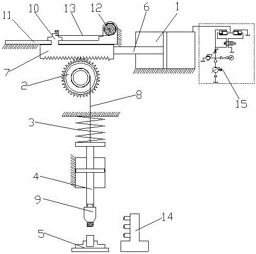
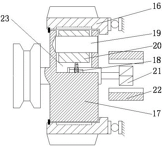
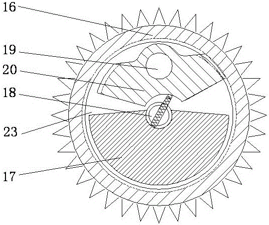
[0017] as attached Figure 1-4 Shown is an electronically controlled crash testing machine according to the present invention, including a plunger cylinder 1, a gear 2, a force storage spring 3, a push rod 4 and a workbench 5; the piston rod 6 of the plunger cylinder 1 is horizontal A rack 7 is connected, the rack 7 is arranged above the gear 2 and meshes with the gear 2, and the gear 2 is driven to rotate by the movement of the rack 7; the gear 2 includes a gear housing 16 and a runner 17; the runner 17 It is arranged in the gear housing 16 and can rotate in the gear housing 16; the runner 17 is provided with a groove 23; the groove 23 is provided with an internal gear block 20 connected by a pin 19; The bottom of the inner gear block 20 is arranged in an arc shape; the central axis of the runner 17 is provided with a spring rod 18; one end of the spring rod 18 extends into th...


PUM


Abstract

The invention discloses an electrically controlled impact tester. The electrically controlled impact tester comprises a plunger type cylinder, a gear, a force accumulation spring, a push rod and a worktable; a rack is horizontally connected to the piston rod of the plunger type cylinder; the rack is arranged above the gear and engaged with the gear; the gear comprises a gear housing and a turning wheel; the turning wheel is arranged in the gear housing and capable of rotating in the gear housing; a groove is formed in the turning wheel; an internal tooth block connected by use of a pin shaft is arranged in the groove; the bottom of the internal tooth block is cambered; a spring rod is arranged at the central axis of the turning wheel; one end of the spring rod extends into the cambered part of the internal tooth block; the spring rod is controlled to rotate by a permanent magnet and an electromagnetic coil; the tail end of the push rod is connected with the force accumulation spring; the push rod is connected with the turning wheel by use of a string; a collision head is arranged on the top of the push rod; the worktable is arranged under the push rod. The electrically controlled impact tester has the advantages that while the influence of hydraulic damping during testing is eliminated, a testing structure is adjusted according to observed test data, and therefore, the operation convenience of the test is effectively improved and the requirements of impact tests with a plurality of variables can be met.

Description

technical field [0001] The invention relates to an electronically controlled collision testing machine, which belongs to the technical field of mechanical engineering. Background technique [0002] At present, the research and development and production of products are mostly developed in the direction of safety, energy saving and environmental protection. Among them, the importance of safety has obviously been set in the first place by major manufacturers, and material reliability is regarded as the key point of product safety research. The important branch has been continuously deepened. Therefore, in order to know the impact resistance of the required materials, the multi-impact crash tester came into being. Among the known testers, there are many difficulties in operation, and there is hydraulic pressure in the collision return. It is difficult to meet the scientific requirements of the test requirements due to the damping effect and the inconsistency with the actual col...

Claims


Application Information

Patent Timeline
Patent Type & Authority Patents(China)
IPC IPC(8): G01N3/307
Inventor 郭彩芬张永康董志万长东宁海霞
Owner SUZHOU VOCATIONAL UNIV
Learn More