Hammer drill

a drill bit and hammer technology, applied in the field of hammer drill bit, can solve the problems of reducing the power of the fan and thereby its cooling effect, and achieve the effects of reducing manufacturing costs, precise shifting of the switching device, and simplifying the construction of the switching devi

Active Publication Date: 2008-02-19
HILTI AG
View PDF16 Cites 34 Cited by
  • Summary
  • Abstract
  • Description
  • Claims
  • Application Information

AI Technical Summary

Benefits of technology

[0009]With such a switching device, the switching between clockwise and counterclockwise operations can be effected with the same control handle that is used for selection of an operational function, which insures a better handling of the hammer drill. Further, the switching between the clockwise and counterclockwise operations is clearly visible and, generally, the operating convenience of the hammer drill is increased.
[0023]Further, the shift plate advantageously has a tooth profile connected, directly or indirectly, with a rotatable matching tool profile provided on the control handle. This insures a particularly precise shifting of the switching device and thereby a reliable switching between the different hammer drill functions.

Problems solved by technology

The drawback of the known hammer drill consists in that a separate switch should be provided for effecting the clockwise and counterclockwise operations and which is poorly visible.
This reduces the power of the fan and thereby its cooling effect.

Method used


Image

  • Hammer drill
  • Hammer drill
  • Hammer drill

Examples


Embodiment Construction

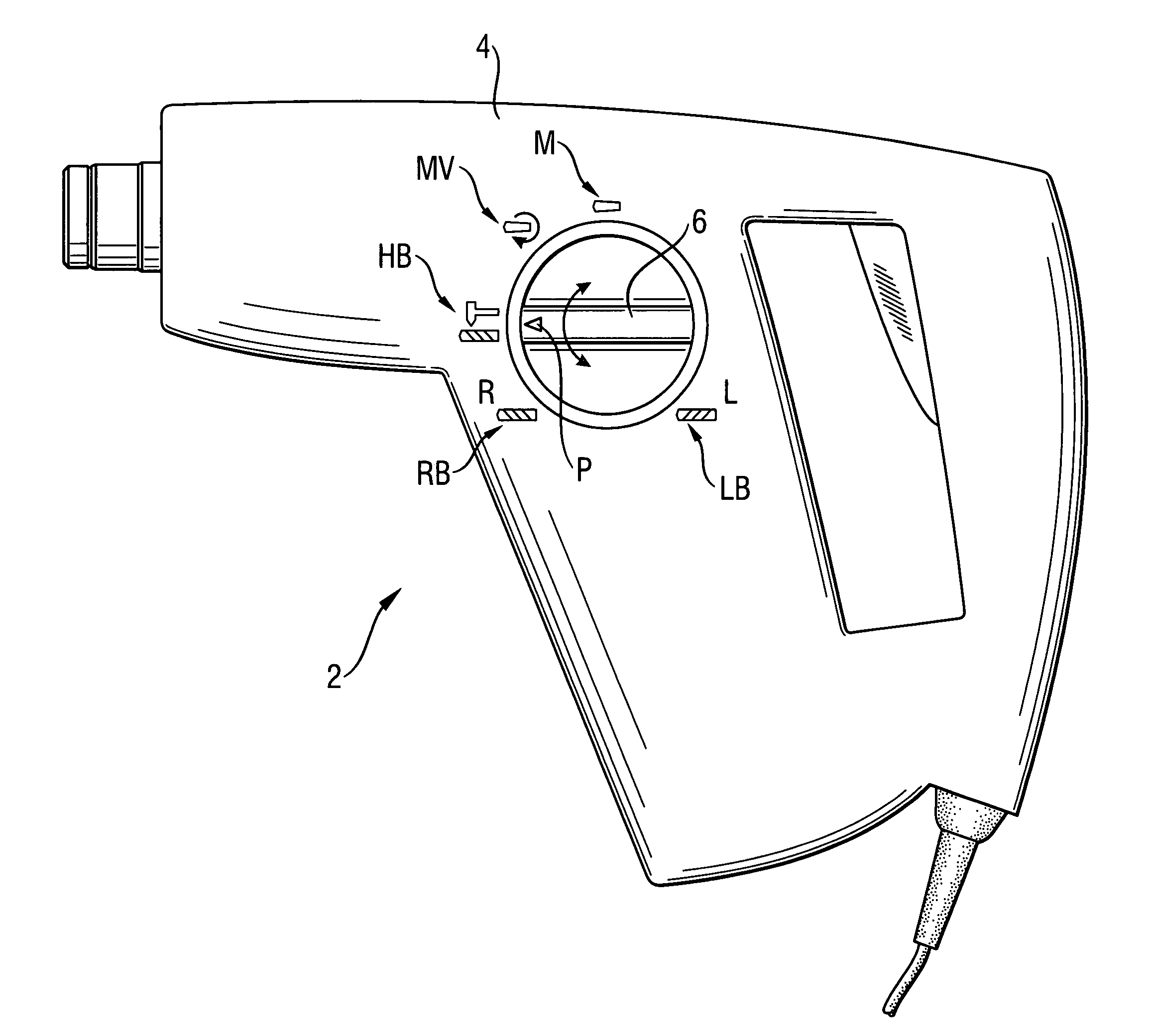
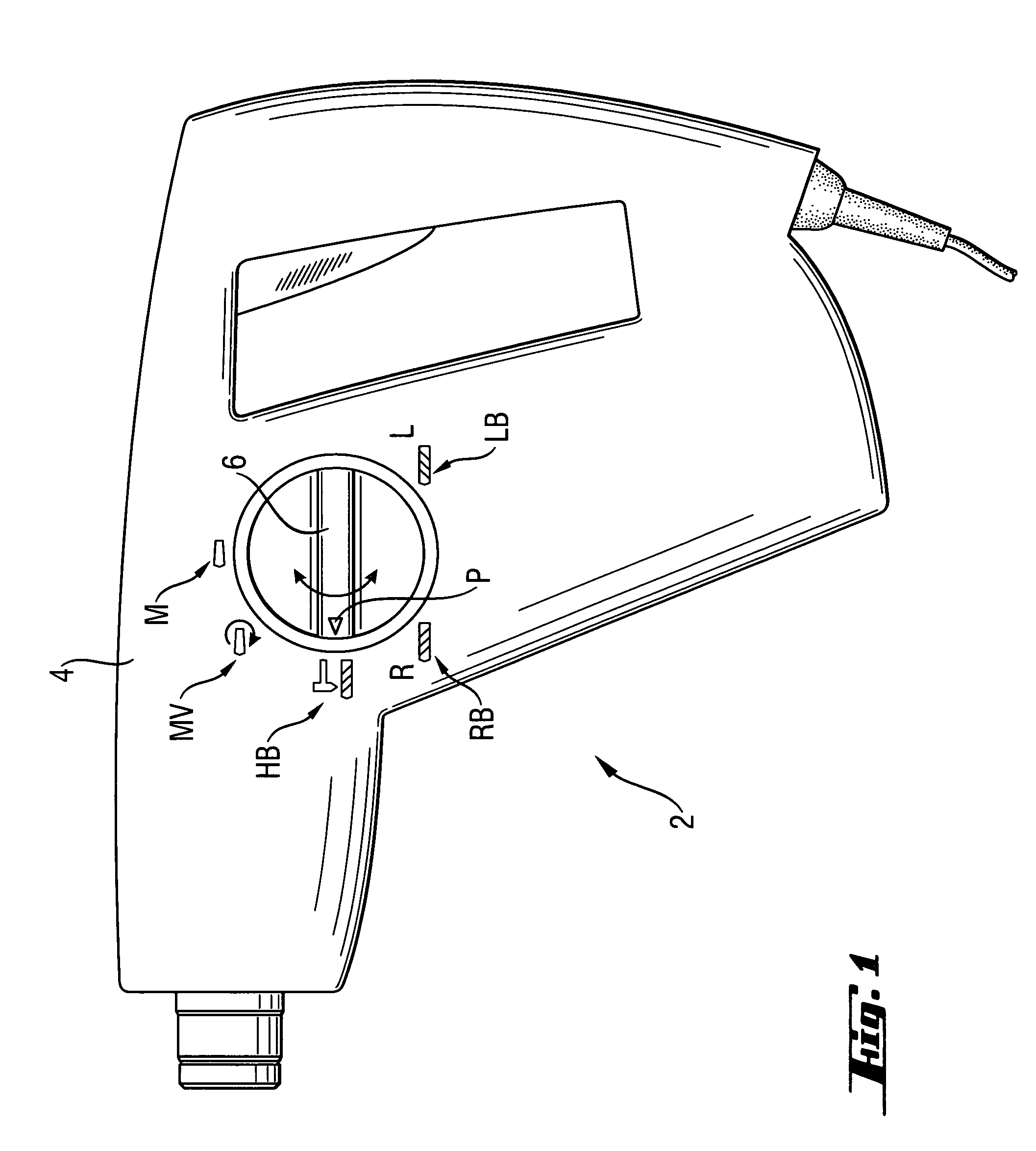
[0035]A hand-held, electrically driven hammer drill 2 according to the present invention, which is shown in FIG. 1, has a housing 4 on which there is provided a control handle 6 in form of a rotary switch for setting up a desired drill function. The control handle 6, together with an arrow symbol P, can be rotated relative to the housing 4, to one of five switching positions which are shown with corresponding symbols on the housing 4. Each switching position corresponds to a different drill function. There are provided chiseling position M, shifting-to-chiseling position MV, rotary-percussion position HB, clockwise drilling position RB, and counterclockwise drilling position LB.

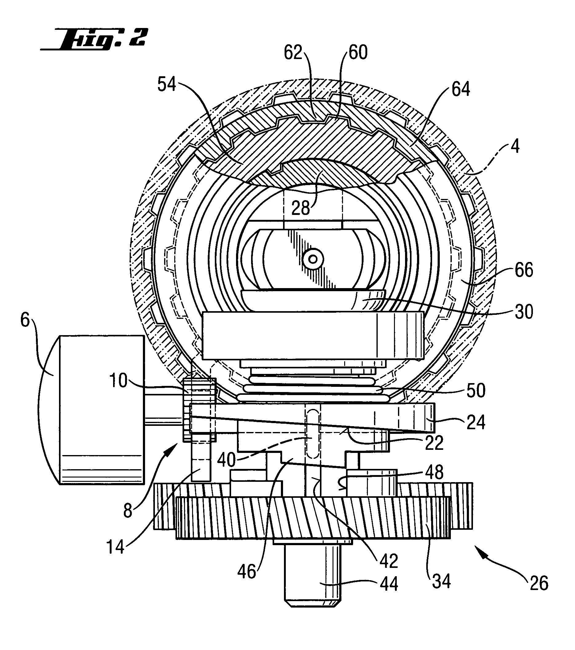
[0036]As shown in FIGS. 2 and 3, the control handle 6 is used for actuation for a switching device 8. The switching device 8 has a pinion 10 connected with the control handle 6 for joint rotation therewith and engaging a tooth profile 12 provided on a shift plate 14. The shift plate 14 has an elongate opening...


PUM

PropertyMeasurementUnit
torqueaaaaaaaaaa
axial displacementaaaaaaaaaa
rotationaaaaaaaaaa

Abstract

A hammer drill (2) includes a clockwise and counterclockwise driven tool spindle (28), a drive pinion (70) operatively connectable with the tool spindle (28) for transmitting a torque thereto, a separate control handle (6) for selecting one of the hammer drill functions including a pure drilling operation, a pure percussion operation, and a rotary-percussion operation), and a switching device (8) which is adjustable in accordance with a position of the control handle (6) and which is shiftable by the control handle (6) in a clockwise rotation position for effecting a pure drilling operation in a clockwise direction and in a counterclockwise rotation position for effecting a pure drilling operation in a counterclockwise direction.

Description

BACKGROUND OF THE INVENTION[0001]1. Field of the Invention[0002]The present invention relates to a hammer drill including a clockwise and counterclockwise driven tool spindle, a drive pinion operatively connectable with the tool spindle for transmitting a torque thereto, a separate control handle for selecting one of drill functions including a pure drilling operation, a pure percussion operation, and a drilling or rotary and percussion operation, and a switching device adjustable in accordance with the position of the control handle.[0003]2. Description of the Prior Art[0004]Hammer drills of the type described above are very operator-friendly because switching between all three drill functions with the same control handle is possible. Moreover, the control handle can be easily arranged in such a way that switching of the drill functions takes place at an easily accessible and well visible location.[0005]German Publication DE-195 45 260 discloses a hammer drill in which switching be...

Claims


Application Information

Patent Timeline
Patent Type & Authority Patents(United States)
IPC IPC(8): E02D7/02B25D16/00B23B45/16B23Q5/00
CPCB25D16/006B25D2211/003B25D2216/0015Y10T74/18032B25D2216/0038B25D2216/0046Y10T74/18024B25D2216/0023
Inventor BRITZ, RORYONTL, RAINER
Owner HILTI AG
Why Eureka
Try Eureka