server

a server and server technology, applied in the field of servers, can solve the problems of uniform management of a plurality of power supplies, high total power consumption, and messy cables in the rack, and achieve the effect of improving operability and heat dissipation efficiency of the server and good layout disposition

Active Publication Date: 2013-03-14
INVENTEC CORP
View PDF24 Cites 34 Cited by
  • Summary
  • Abstract
  • Description
  • Claims
  • Application Information

AI Technical Summary

Benefits of technology

[0009]Accordingly, the present invention is directed to a server, whose rack has good layout disposition so as to improve operability and heat dissipation efficiency of the server.
[0026]Based on the above description, in the embodiment of the present invention, through the internal layout and the relevant disposition of the rack, and the electric power transmission unit disposed in the rack, the server uniformly supplies power to the apparatus units including the communication exchange unit and the rack control unit in the rack, thereby conveniently and effectively performing entire management and power consumption control, and effectively saving the number of cables of each apparatus unit and the layout thereof. In addition to simplifying the internal layout of the rack to improve the operation convenience of the server unit, this practice can achieve good heat dissipation efficiency in cooperation with the particularly designed heat dissipation air passage. Further, the centralized fan system is also convenient for uniform management and control and energy consumption reduction.

Problems solved by technology

Therefore, it is difficult to uniformly manage a plurality of power supplies in a rack, and independent operation of each power supply causes the total power consumption to be high.
Each apparatus unit in the existing rack is connected to a power supply through a cable, and as the number of apparatus units increases, cables in the rack accordingly become messy.
These disposed cables, which are not sorted out easily, complicate efforts to replace or service a server unit.
Meanwhile, because flowing of an air flow is obstructed, the heat dissipation efficiency of the server unit is reduced.
When the plurality of internal power supplies is in operation, they also generate a large amount of heat, which may not be optimal given the heat dissipation design of the rack.

Method used


Image

  • server
  • server
  • server

Examples


Embodiment Construction

[0044]Reference will now be made in detail to the present embodiments of the invention, examples of which are illustrated in the accompanying drawings. Wherever possible, the same reference numbers are used in the drawings and the description to refer to the same or like parts.

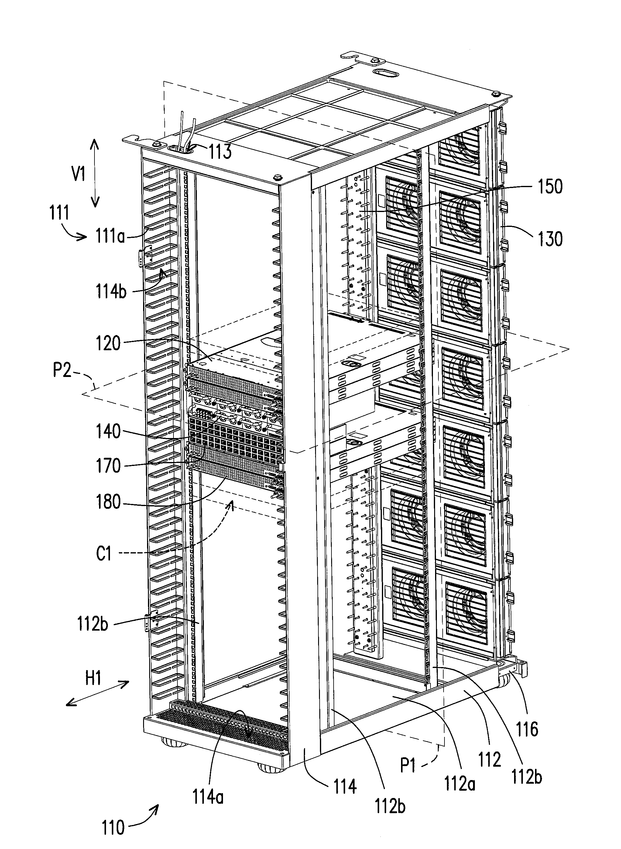
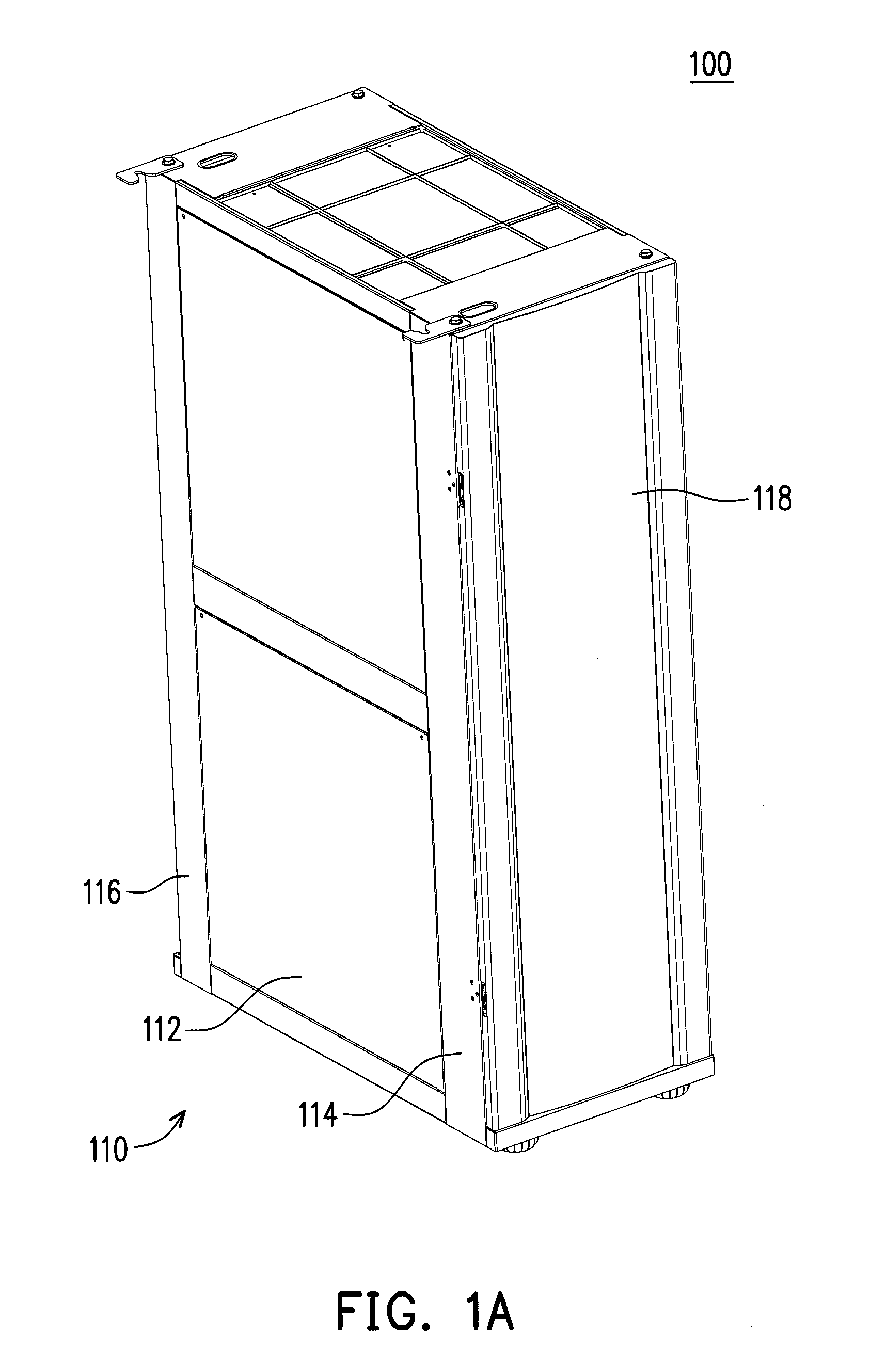
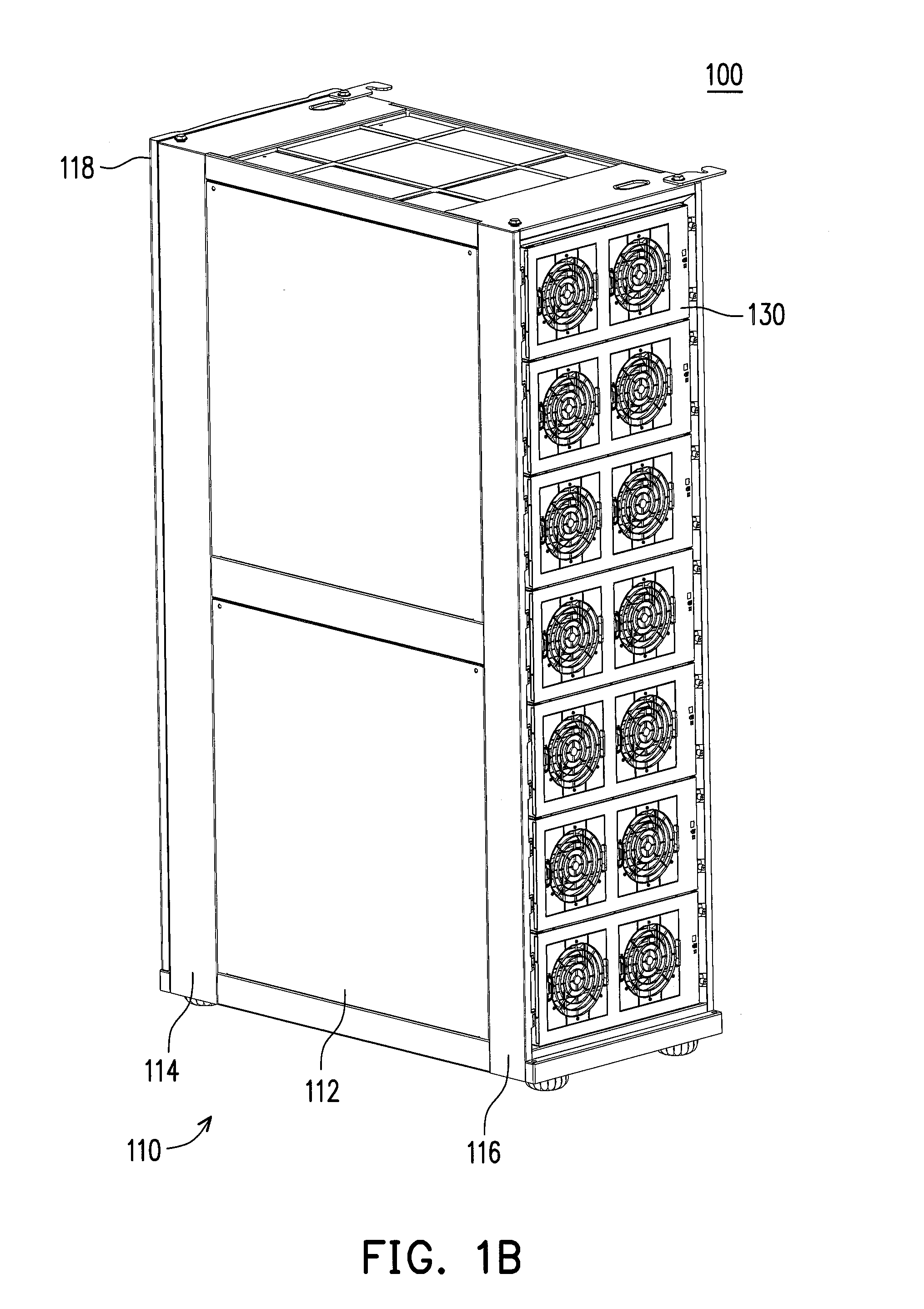
[0045]FIG. 1A and FIG. 1B are schematic views of a server according to an embodiment of the present invention at different viewing angles respectively. FIG. 2A and FIG. 2B are schematic views of a part of components in the server in FIG. 1A and FIG. 1B at different viewing angles respectively. Referring to FIG. 1A, FIG. 1B, FIG. 2A and FIG. 2B, in this embodiment, a server 100 includes a rack 110, at least one server unit 120, a plurality of fan modules 130, a power supply unit 140, an electric power transmission unit 150, at least one communication exchange unit 170 and at least one rack control unit 180. The rack 110 has a plurality of shelving spaces C1.

[0046]The number of power supply units 140, server uni...


PUM


Abstract

A server includes a rack, at least one server unit, at least one communication exchange unit, at least one rack control unit and an electric power transmission unit. The rack has a plurality of shelving spaces. The server unit, the communication exchange unit, and the rack control unit are moved into or moved out of a corresponding shelving space along a horizontal axis, respectively. The server unit is communicatively connected to the communication exchange unit, and communicates with the rack control unit through the communication exchange unit. The electric power transmission unit is disposed in the rack and runs adjacent to the shelving spaces along a vertical axis. After the server unit, the communication exchange unit and the rack control unit are moved into corresponding shelving spaces, the server unit, the communication exchange unit and the rack control unit are electrically connected to the electric power transmission unit.

Description

CROSS-REFERENCE TO RELATED APPLICATION[0001]This application claims the priority benefit of China application serial no. 201110266007.4, filed Sep. 8, 2011. The entirety of the above-mentioned patent application is hereby incorporated by reference herein and made a part of this specification.BACKGROUND OF THE INVENTION[0002]1. Field of the Invention[0003]The present invention relates to a server, in particular, to a server having both electric power and heat dissipation transmission layouts.[0004]2. Description of Related Art[0005]A server is a core computer serving computers in a network system, may provide functions such as a magnetic disk and a print service required by a network user, and meanwhile may also be used for clients to share resources in a network environment with each other. A basic architecture of the server is approximately the same as that of a general personal computer, and is formed of components such as a Central Processing Unit (CPU), a memory and an Input / Out...

Claims


Application Information

Patent Timeline
Patent Type & Authority Applications(United States)
IPC IPC(8): H05K7/20H05K7/16
CPCH05K7/1492G06F1/20G06F2200/201H05K7/20563H05K7/20736H05K7/20727
Inventor WANG, SHI-FENG
Owner INVENTEC CORP
Why Eureka
Try Eureka