Continuously Adjustable Fiber Attenuator
An optical fiber attenuator, optical fiber technology, applied in optics, instruments, optical components, etc., can solve problems such as troublesome operation, and achieve the effect of easy operation, stable type, and simple structure
- Summary
- Abstract
- Description
- Claims
- Application Information
AI Technical Summary
Problems solved by technology
Method used
Image
Examples
Embodiment 1
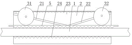
[0017] Such as figure 1 The continuously adjustable optical fiber attenuator shown includes a housing 2, an optical fiber 1 and two relative microbend deformers, the optical fiber 1 is located between the two microbend deformers, and a useful For the groove where the optical fiber 1 is placed, the microbend deformer includes an upper platen 5 with corrugations at the bottom and a lower corrugated surface 24 at the bottom of the groove, and the side walls of the groove are respectively provided with symmetrical The first guide groove 21 and the second guide groove 22, the first guide groove 21 and the second guide groove 22 are not parallel to the central axis of the optical fiber 1 and have the same angle with the optical fiber 1, the first guide groove A first adjusting cylinder 31 for adjusting the upper pressing plate 5 is movably arranged between the grooves 21, and a second adjusting cylinder 32 for adjusting the upper pressing plate 5 is movably arranged between the seco...
Embodiment 2
[0019] Such as figure 1 The continuously adjustable fiber attenuator shown in this embodiment is optimized on the basis of embodiment 1 in order to ensure the accuracy of the fiber attenuator and the length of the housing. The center of the first guide groove 21 and the optical fiber 1 The included angle between the axes is greater than 10 degrees and less than 45 degrees.
Embodiment 3
[0021] Such as figure 1 For the continuously adjustable optical fiber attenuator shown, in order to directly read the positions of the first adjustment cylinder and the second adjustment cylinder, this embodiment is optimized on the basis of the above embodiment, that is, the degree of the scale 23 is along the The line of symmetry of the first guide groove 21 and the second guide groove 22 gradually increases or decreases along both sides, and the scale is parallel to the lower corrugated surface, and is set at the line of symmetry of the first guide groove 21 and the second guide groove 22 The reading symmetry line of the scale, that is, where it is 0 or the maximum value of the scale.
PUM
 Abstract
Description
Claims
Application Information
 - R&D
- Intellectual Property
- Life Sciences
- Materials
- Tech Scout
- Unparalleled Data Quality
- Higher Quality Content
- 60% Fewer Hallucinations
Browse by: Latest US Patents, China's latest patents, Technical Efficacy Thesaurus, Application Domain, Technology Topic, Popular Technical Reports.
© 2025 PatSnap. All rights reserved.Legal|Privacy policy|Modern Slavery Act Transparency Statement|Sitemap|About US| Contact US: help@patsnap.com

