Easily Adjustable Fiber Optic Attenuators

A technology of optical fiber attenuator and optical fiber, which is applied in the direction of optical waveguide coupling, etc., can solve problems such as troublesome operation, and achieve the effects of easy observation, guaranteed stability, and easy adjustment and operation

Inactive Publication Date: 2017-02-15
CHENGDU MAKEMODE COMM TECH
View PDF5 Cites 0 Cited by
  • Summary
  • Abstract
  • Description
  • Claims
  • Application Information

AI Technical Summary

Problems solved by technology

With the optical fiber attenuator of this structure, when adjusting the distance of the microbending deformer, an adjuster is required, that is, the adjuster is adjusted to make the microbending deformer move along the guide rail to adjust the distance. According to the actual use, you can use The regulator is realized by manual, motor, voltage, magnetic field, etc. When the manual method is used, the adjustment rod of the connector is provided with threads, and the adjustment of the distance of the micro-deformer is realized by rotating the adjustment rod, which is very troublesome to operate

Method used


Image

  • Easily Adjustable Fiber Optic Attenuators
  • Easily Adjustable Fiber Optic Attenuators

Examples


Embodiment 1

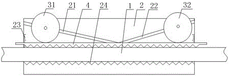
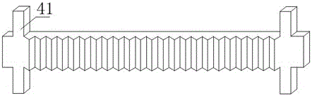
[0018] Such as figure 1 and figure 2 The shown easy-to-adjust fiber attenuator includes a housing 2, an optical fiber 1 and a micro-bend deformer for bending the optical fiber 1. The housing 2 is provided with a groove for placing the optical fiber 1. The micro-bending deformation The device includes an upper platen 4 with a corrugated surface at the bottom and a lower corrugated surface 24 at the bottom of the groove that is staggered from the corrugated surface of the upper platen 4, and the two inner groove walls of the groove are provided with first guide grooves 21 With the second guide groove 22 symmetrical to the first guide groove 21, the included angles between the first guide groove 21 and the second guide groove 22 and the central axis of the optical fiber 1 are equal, and the first guide groove 21 The first adjustment cylinder 31 for adjusting the upper pressing plate 4 is arranged between them, the second adjusting cylinder 32 for adjusting the upper pressing pl...

Embodiment 2

[0020] Such as figure 1 and figure 2 The easy-to-adjust fiber attenuator shown in this embodiment is optimized on the basis of embodiment 1 in order to ensure the accuracy of the fiber attenuator and the length of the housing, that is, the distance between the first guide groove 21 and the central axis of the optical fiber 1 The included angle is greater than 10 degrees and less than 40 degrees.

Embodiment 3

[0022] Such as figure 1 and figure 2 For the easy-to-adjust fiber attenuator shown in this embodiment, a set of data is optimized on the basis of Embodiment 2, that is, the included angle between the first guide groove 21 and the central axis of the optical fiber 1 is 35 degrees.


PUM


Abstract

The invention discloses an easily-adjustable optical fiber attenuator which comprises a casing, an optical fiber and a microbend deformer for bending the optical fiber. A groove for storing the optical fiber is formed in the casing, and the microbend deformer comprises an upper press plate with a corrugated surface arranged at the bottom and a lower corrugated surface positioned at the bottom of the groove and staggered with the corrugated surface of the upper press plate. The two inner groove walls of the groove are each provided with a first guide groove and a second guide groove symmetrical to the first guide groove, and an included angle formed by each first guide groove and the center axis of the optical fiber is identical to an included angle formed by each second guide groove and the center axis of the optical fiber. A first adjustment cylinder for adjusting the upper press plate is arranged between the first guide grooves, a second adjustment cylinder for adjusting the upper press plate is arranged between the second guide grooves, the length of the upper press plate is larger than that of the groove, limit strips are arranged at the two ends of the upper press plate, outside the groove, and scales for displaying the position of the upper press plate are arranged on the groove. The easily-adjustable optical fiber attenuator is stable in structure. In addition, the curvature of the optical fiber can be changed by sliding the first adjustment cylinder and the second adjustment cylinder, so that the easily-adjustable optical fiber attenuator is easy to operate.

Description

technical field [0001] The invention relates to the field of optical fiber attenuators, in particular to an easily adjustable optical fiber attenuator. Background technique [0002] Optical fiber attenuators are passive components widely used in the field of optical communications. It is used to attenuate the input optical power, avoiding the distortion of the optical receiver due to the super strong input optical power. In order to achieve continuous adjustment, the existing optical fiber attenuator adopts a structure with the publication number CN 1658023 A, which uses a micro-bend deformer to realize the bending degree of the optical fiber, so as to realize the modulation of the signal light intensity in the optical fiber, so as to realize Adjustable light attenuation. With the optical fiber attenuator of this structure, when adjusting the distance of the microbending deformer, an adjuster is required, that is, the adjuster is adjusted to make the microbending deformer ...

Claims


Application Information

Patent Timeline
Patent Type & Authority Patents(China)
IPC IPC(8): G02B6/26
Inventor 蔡义炜郭仁祥李道斌
Owner CHENGDU MAKEMODE COMM TECH
Why Eureka
Try Eureka