
Graphical indicator

An image index and micro-image technology, which is applied in image communication, image enhancement, image data processing, etc., can solve the problems of image index 102 recognition rate drop, reduce the ability to carry index data, etc., and achieve the best recognition rate.

Active Publication Date: 2014-11-19
SONIX TECH
View PDF6 Cites 8 Cited by
  • Summary
  • Abstract
  • Description
  • Claims
  • Application Information

AI Technical Summary

Problems solved by technology

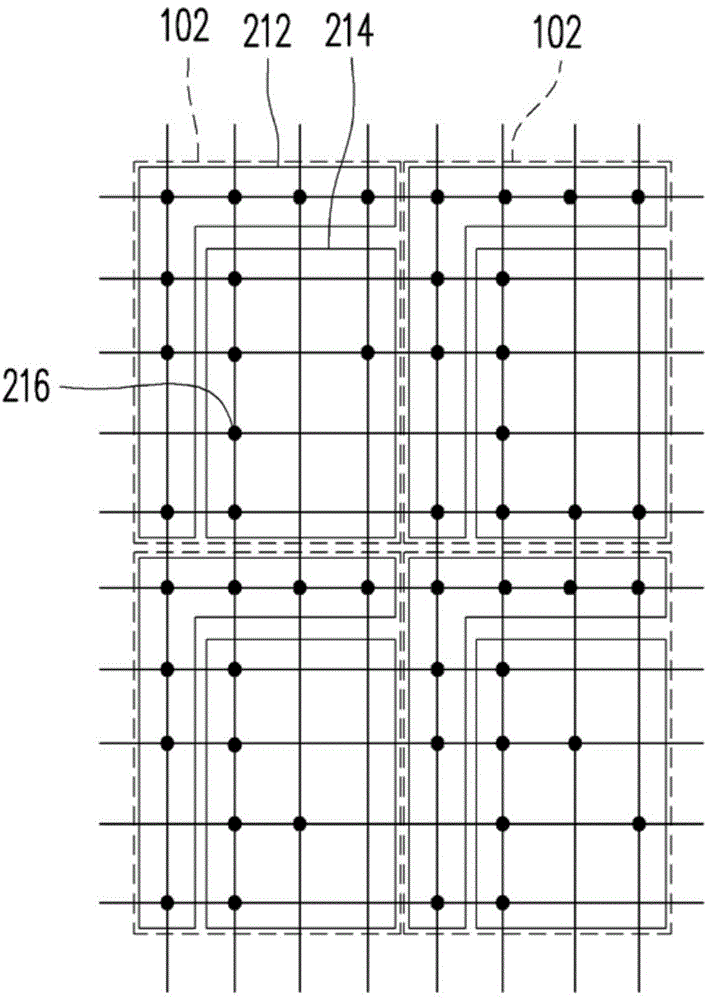
However, if the header area 212 is excessively expanded to carry header information in the image indicator 102, the ability of the image indicator 102 to carry indicator data will be reduced instead.
On the other hand, if the micro-image units 216 in the content data area 214 are arranged too densely, or some micro-image units 216 in the content data area 214 are too far away from the header area 212, the image index 102 will also appear in the image. Recognition rate drops in recognition

Method used


Image

  • Graphical indicator
  • Graphical indicator
  • Graphical indicator

Examples


Embodiment Construction

[0057] Figure 2A It is a schematic diagram of image indicators drawn according to an embodiment of the present invention. Please refer to Figure 2A , in this embodiment, the image indicator 20 includes a linear area 220 and an array area 240 . The linear area 220 includes a plurality of blocks 260A, and each block 260A has a header micro image unit A. As shown in FIG. The array area 240 and the linear area 220 have blocks 260A and 260B to form an index matrix 280 , and the dimension of the index matrix 280 is M×N, where M and N are positive integers greater than 2, respectively. In this embodiment, M is 5 and N is 4, but the present invention is not limited thereto. The array region 240 is composed of a plurality of sub-linear array regions 242 parallel to the linear region 220, each sub-linear array region 242 has a plurality of blocks 260A and 260B, and includes at least one header micro-image unit A and a plurality of The data micro image units B are respectively arra...


PUM


Abstract

A graphical indicator comprises a plurality of first header blocks, a plurality of second header blocks and a plurality of data blocks to form an indicator matrix. Each of the first and second header blocks includes a header graphical micro-unit, and each data block includes a data graphical micro-unit. An array region is formed by the second header blocks and the data blocks. A first virtual line is formed at virtual centers of the first header blocks, and a second virtual line is formed at virtual centers of the second header blocks. The included angle between the first and second virtual lines is smaller than 90 degrees.

Description

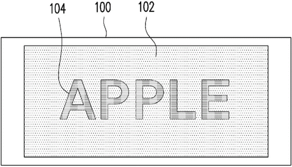
technical field [0001] The present invention relates to an image index that can be read by pattern / image recognition, and the image index corresponds to an index data. Background technique [0002] With the advancement of printing technology and electronic technology, the technology of hiding image indicators in text information or image information visible to the naked eye has been widely used in daily life. Figure 1A It is a schematic diagram of coexistence of image indicators and main information drawn according to known techniques. Such as Figure 1A As shown, a graphical indicator 102 is formed on an object surface 100 . The graphical indicator 102 is composed of many graphical micro-units. Since the micro-graphic units are quite small, they are easily ignored visually or interpreted as background color by human eyes. The image index 102 and main information 104 (such as the character pattern “APPLE” in FIG. 1 ) are jointly formed on the surface 100 of an object such ...

Claims


Application Information

Patent Timeline
IPC IPC(8): G06T5/00
CPCG06K19/06037G06K19/06131G06K19/06178H04N1/32219H04N1/32251G06K19/06G09F9/33G09F15/0025Y10S362/80
Inventor 李政达蔡彰哲黄资峰
Owner SONIX TECH
Learn More