Automatic pedal system of electric unicycle

An electric unicycle and pedal technology, which is applied to pedals, motor vehicles, bicycles, etc., can solve the problems of unsanitary and inconvenience when touching the pedals with bare hands, and achieve the effect of strong practicability and convenient deployment.

Active Publication Date: 2014-11-26
CHANGSHU INTELLIGENT LASER EQUIP RES INST CO LTD
View PDF3 Cites 11 Cited by
  • Summary
  • Abstract
  • Description
  • Claims
  • Application Information

AI Technical Summary

Problems solved by technology

The rise of self-balancing electric unicycles is about to trigger a new transportation revolution; the opening and closing of the pedals of existing electric unicycles requires manual operation, which is very inconvenient, and there is generally dust or dirt when the pedals pass through the soles of the shoes. Very unhygienic to touch the pedals

Method used


Image

  • Automatic pedal system of electric unicycle
  • Automatic pedal system of electric unicycle
  • Automatic pedal system of electric unicycle

Examples


Embodiment 1

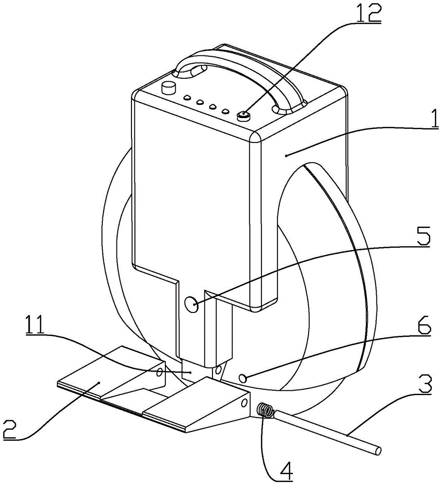
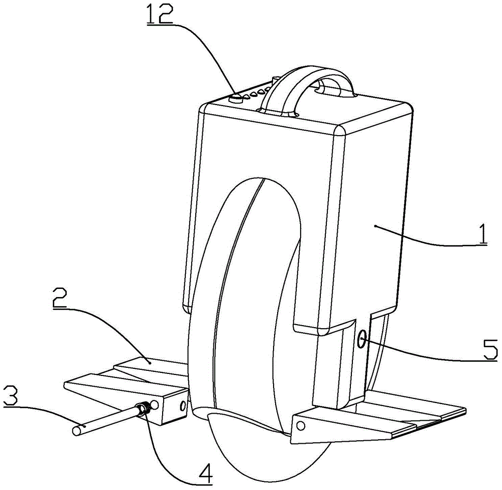
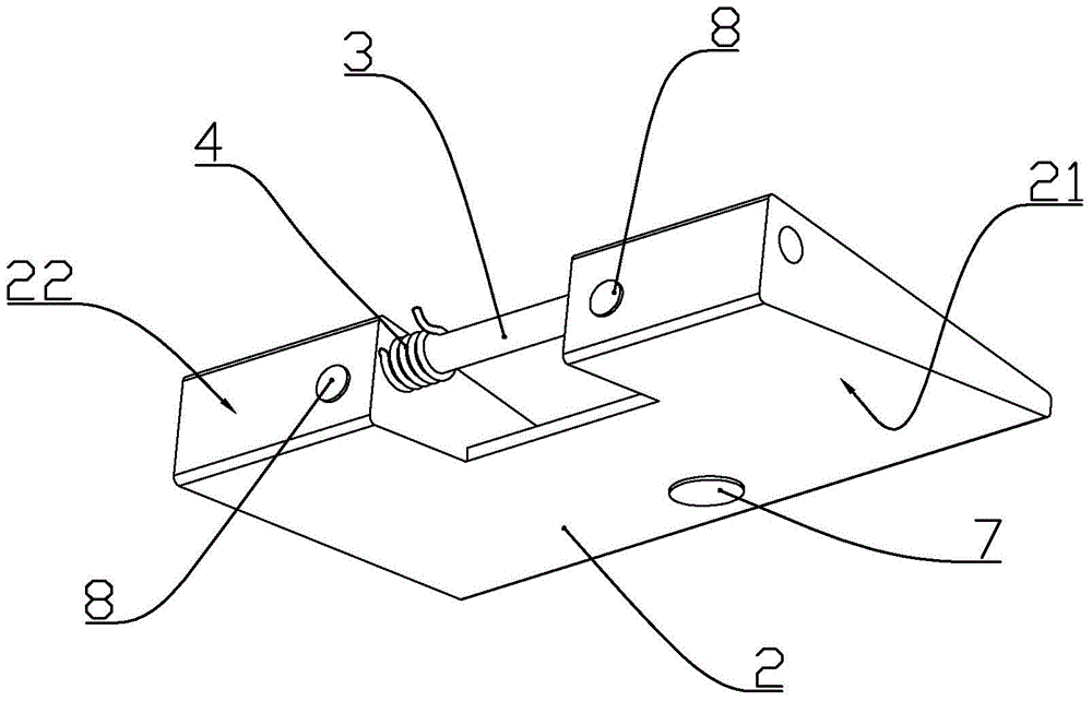
[0013] according to Figure 1 to Figure 4 As shown, the automatic pedal system of a kind of electric unicycle described in the present embodiment includes two pedals 2 connected to both sides of the vehicle body 1 through the connecting shaft 3 rotation, and is installed on the upper part of the vehicle body in order to control the start and stop of the unicycle. Power switch 12, the first permanent magnet 7 is installed on the lower wall surface 21 of described pedal, and the first electromagnet 5 that cooperates with the first permanent magnet is installed on both sides of vehicle body, and described first electromagnet is in the pedal retracted state When the first electromagnet is not energized, it is opposite to the first permanent magnet. When the first electromagnet is not energized, it is attracted to the first permanent magnet. When the first electromagnet is energized, it is mutually exclusive with the first permanent magnet; The position below is equipped with the s...

Embodiment 2

[0022] according to Figure 1 to Figure 4 As shown, the automatic pedal system of a kind of electric unicycle described in the present embodiment includes two pedals 2 connected to both sides of the vehicle body 1 through the connecting shaft 3 rotation, and is installed on the upper part of the vehicle body in order to control the start and stop of the unicycle. Power switch 12, the first permanent magnet 7 is installed on the lower wall surface 21 of described pedal, and the first electromagnet 5 that cooperates with the first permanent magnet is installed on both sides of vehicle body, and described first electromagnet is in the pedal retracted state When the first electromagnet is not energized, it is opposite to the first permanent magnet. When the first electromagnet is not energized, it is attracted to the first permanent magnet. When the first electromagnet is energized, it is mutually exclusive with the first permanent magnet; The position below is equipped with the s...

Embodiment 3

[0028] according to Figure 1 to Figure 4 As shown, the automatic pedal system of a kind of electric unicycle described in the present embodiment includes two pedals 2 connected to both sides of the vehicle body 1 through the connecting shaft 3 rotation, and is installed on the upper part of the vehicle body in order to control the start and stop of the unicycle. Power switch 12, the first permanent magnet 7 is installed on the lower wall surface 21 of described pedal, and the first electromagnet 5 that cooperates with the first permanent magnet is installed on both sides of vehicle body, and described first electromagnet is in the pedal retracted state When the first electromagnet is not energized, it is opposite to the first permanent magnet. When the first electromagnet is not energized, it is attracted to the first permanent magnet. When the first electromagnet is energized, it is mutually exclusive with the first permanent magnet; The position below is equipped with the s...


PUM


Abstract

The invention discloses an automatic pedal system of an electric unicycle. The automatic pedal system comprises two pedals rotationally connected to the two sides of a unicycle body through a connecting shaft, and a power switch installed on the upper portion of the unicycle body and used for controlling starting and stopping of the unicycle. The lower walls of the pedals are provided with first permanent magnets, the two sides of the unicycle are provided with first electromagnets working in cooperation with the first permanent magnets, the first electromagnets are attracted to the first permanent magnets when not powered, and the first electromagnets are repelled to the first permanent magnets when powered. Second permanent magnets are installed at the positions, below the connecting shaft, of the inner side walls of the pedals, the two sides of the unicycle body are provided with second electromagnets working in cooperation with the second permanent magnets, the second electromagnets are attracted to the second permanent magnets when not powered, and the second electromagnets are repelled to the second permanent magnets when powered. The power switch of the unicycle is used for controlling the electromagnets to drive the pedals to be unfolded and folded, and the automatic pedal system is convenient to use and high in practicality.

Description

technical field [0001] The invention belongs to the structural field of an electric unicycle, and in particular relates to a unicycle whose pedals can be automatically lowered and stowed. Background technique [0002] Self-balancing electric unicycle is a means of transportation with electric drive and self-balancing function. With the rapid development of society today, traffic congestion has become a common phenomenon. Electric unicycles replace bicycles and electric vehicles as transportation tools. The rise of self-balancing electric unicycles is about to trigger a new transportation revolution; the opening and closing of the pedals of existing electric unicycles requires manual operation, which is very inconvenient, and there is generally dust or dirt when the pedals pass through the soles of the shoes. It is very unhygienic to touch the pedals. Contents of the invention [0003] The technical problem to be solved by the present invention is to provide an...

Claims


Application Information

Patent Timeline
Patent Type & Authority Applications(China)
IPC IPC(8): B62J25/00
CPCB62J25/00B62K11/00
Inventor 李陈
Owner CHANGSHU INTELLIGENT LASER EQUIP RES INST CO LTD
Why Eureka
Try Eureka