Fixed hydraulic lifting machine

A lift, fixed technology, applied in the direction of lifting frame, lifting device, etc., can solve the problems of structural deformation, asynchronous, affecting the accuracy of lifting position, etc., and achieve the effect of simple structure, low cost and convenient implementation.

Active Publication Date: 2016-02-24
苏州市康鼎升降机械有限公司
View PDF7 Cites 9 Cited by
  • Summary
  • Abstract
  • Description
  • Claims
  • Application Information

AI Technical Summary

Problems solved by technology

Due to the many hinge points of the double scissors structure, each hinge point has a movable gap. The accumulation of the movable gap and the amplification of the longer scissor arm are prone to structural deformation, which affects the accuracy of its lifting position.
When multiple multi-stage telescopic hydraulic cylinders are used at the same time, due to the error of the mechanical processing of the parts and the resistance error of the hydraulic oil in the pipeline, the impact on the work of the cylinder rod with a small diameter in the hydraulic cylinder is more obvious, generally from the second When the first-stage cylinder rod begins to expand and contract, it often appears out of sync, which affects the stability of the equipment's lifting

Method used


Image

  • Fixed hydraulic lifting machine
  • Fixed hydraulic lifting machine
  • Fixed hydraulic lifting machine

Examples


Embodiment Construction

[0023] The present invention will be described in further detail below in conjunction with the accompanying drawings and specific embodiments.

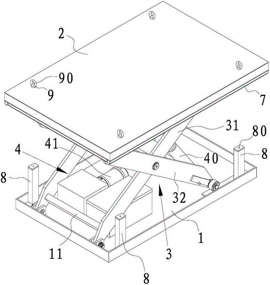
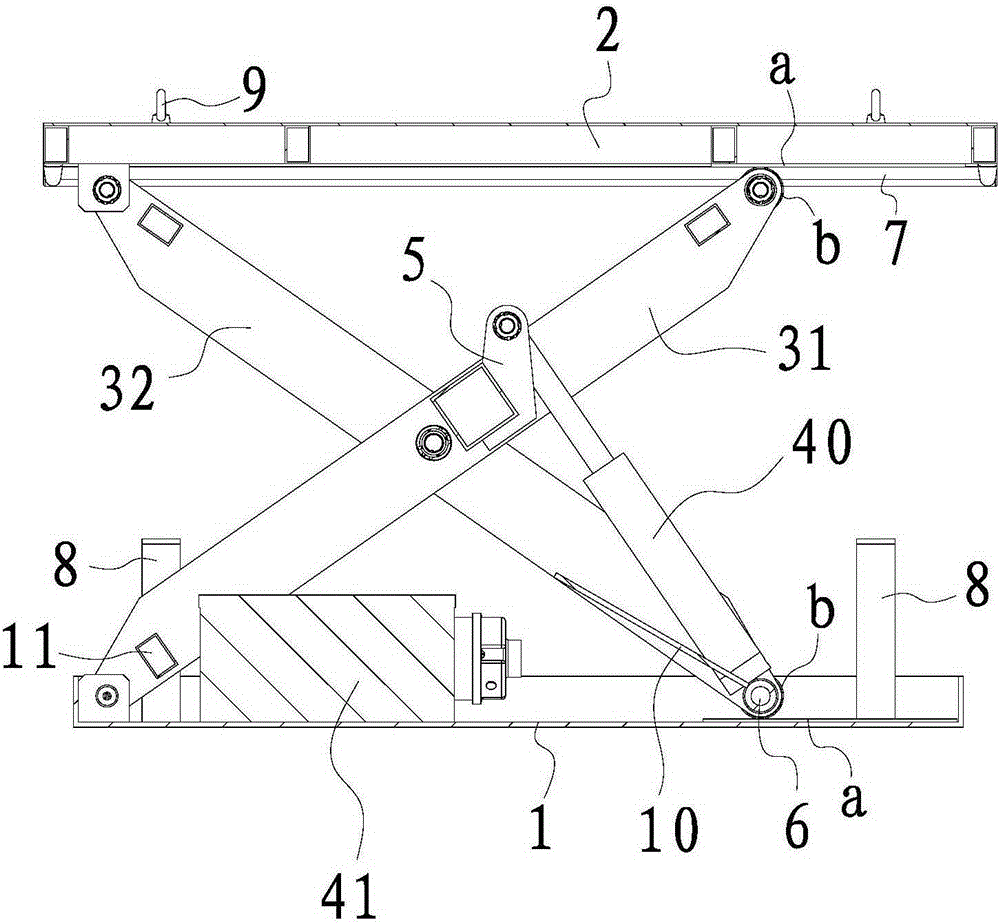
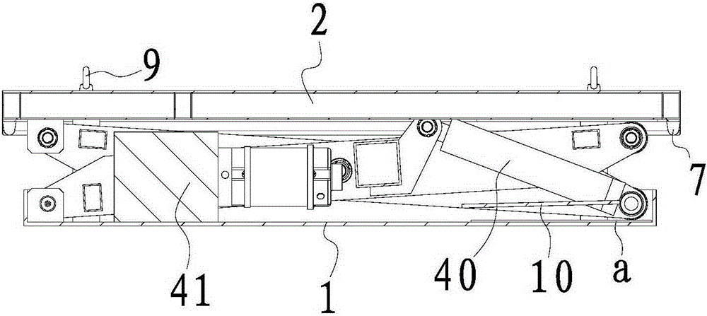
[0024] see Figure 1 to Figure 5 , the fixed hydraulic lift provided by this embodiment includes a base 1, a carrying platform 2, support arms 3 arranged on both sides of the base 1 to cross inside and outside, and a drive mechanism 4 for driving the support arms 3 to expand or retract relatively.

[0025] The support arm 3 includes a first support arm 31 and a second support arm 32 that intersect from the inside and outside of the middle and are rotatably connected. the bottom of the bottom; the lower end of the second arm 32 is slidably arranged on the base 1 , and the upper end is rotatably arranged on the bottom of the carrying platform 2 .

[0026] The hydraulic lift also includes a first pole 5 for synchronously connecting the lower ends of the second arms 32 on both sides, a second pole 6 for synchronously connecting t...


PUM


Abstract

The invention relates to a fixed hydraulic lifting machine which comprises a base, a bearing platform, supporting arms and a driving mechanism, wherein the supporting arms are positioned on two sides of the base and are arranged in an internal-external crossed manner; the driving mechanism is used for driving the supporting arms to being relatively unfolded or folded; each supporting arm comprises a first supporting arm and a second supporting arm; the first supporting arms and the second supporting arms are arranged in an internal-external crossed manner and rotationally connected with each other; the lower end parts of the first supporting arms are rotationally arranged on the base; the upper end parts of the first supporting arms are arranged at the bottom of the bearing platform in a sliding manner; the lower end parts of the second supporting arms are arranged on the base in a sliding manner; the upper end parts of the second supporting arms are rotationally arranged at the bottom of the bearing platform; the hydraulic lifting machine also comprises first supporting rods and second supporting rods; the first supporting rods are used for connecting the lower end parts of the second supporting arms on two sides synchronously; the second supporting rods are used for connecting the middle upper parts of the supporting arms on two sides synchronously; the driving mechanism comprises hydraulic cylinders and a hydraulic pump station; two end parts of the hydraulic cylinder are respectively and rotationally arranged on the first supporting rods and the second supporting rods; and the hydraulic pump station is arranged on the base, and is positioned between the supporting arms on two sides. The fixed hydraulic lifting machine can realize the lifting of the bearing platform relatively stably.

Description

technical field [0001] The invention relates to a fixed hydraulic lift. Background technique [0002] The current fixed hydraulic lift is widely used in many industries due to its almost unlimited stroke and strong load capacity. The underground sealed horizontal garbage compression and transfer equipment gradually promoted in the environmental sanitation department, because of its long lifting stroke and large load capacity, many manufacturers have adopted a double scissors structure and a hydraulic lifting mechanism with multiple multi-stage telescopic hydraulic cylinders. lift. Due to the many hinge points of the double scissors structure, there is a movable gap at each hinge point. The accumulation of the movable gap and the enlargement of the longer scissor arm are prone to structural deformation, which affects the accuracy of its lifting position. When multiple multi-stage telescopic hydraulic cylinders are used at the same time, due to the error of the mechanical pr...

Claims


Application Information

Patent Timeline
Patent Type & Authority Applications(China)
IPC IPC(8): B66F7/08B66F7/28
Inventor 袁晓新袁永康
Owner 苏州市康鼎升降机械有限公司
Why Eureka
Try Eureka