
Vacuum chuck and bracket type vacuum adsorption equipment provided with vacuum chuck

A technology of vacuum adsorption and vacuum suction cups, which is applied in the direction of manipulators, chucks, manufacturing tools, etc., can solve the problem of damage to the surface of the material, achieve the effect of increasing friction and avoiding scratches on the workpiece

Inactive Publication Date: 2014-12-03
UTECHZONE CO LTD
View PDF10 Cites 4 Cited by
  • Summary
  • Abstract
  • Description
  • Claims
  • Application Information

AI Technical Summary

Problems solved by technology

In addition, Chinese Taiwan Patent No. 201240009 discloses a non-contact vacuum suction cup. The suction cup is provided with at least one anti-collision pad on the adsorption surface. The purpose of transferring the blank can be achieved, and in the state of use, the blank may still collide with the suction cup or the anti-collision pad on the suction cup due to the vibration generated during the transfer and turning over, causing damage to the surface of the blank. Repeated collisions with crash pads and damage to the surface of the blanks occur

Method used


Image

  • Vacuum chuck and bracket type vacuum adsorption equipment provided with vacuum chuck
  • Vacuum chuck and bracket type vacuum adsorption equipment provided with vacuum chuck
  • Vacuum chuck and bracket type vacuum adsorption equipment provided with vacuum chuck

Examples


Embodiment Construction

[0037] The structural features and operation modes of the present invention, together with illustrations, are described below for review reference. Furthermore, for the convenience of description, the proportions of the drawings in the present invention are not necessarily drawn according to the actual scale, but may be exaggerated. These drawings and their proportions are not intended to limit the scope of the present invention.

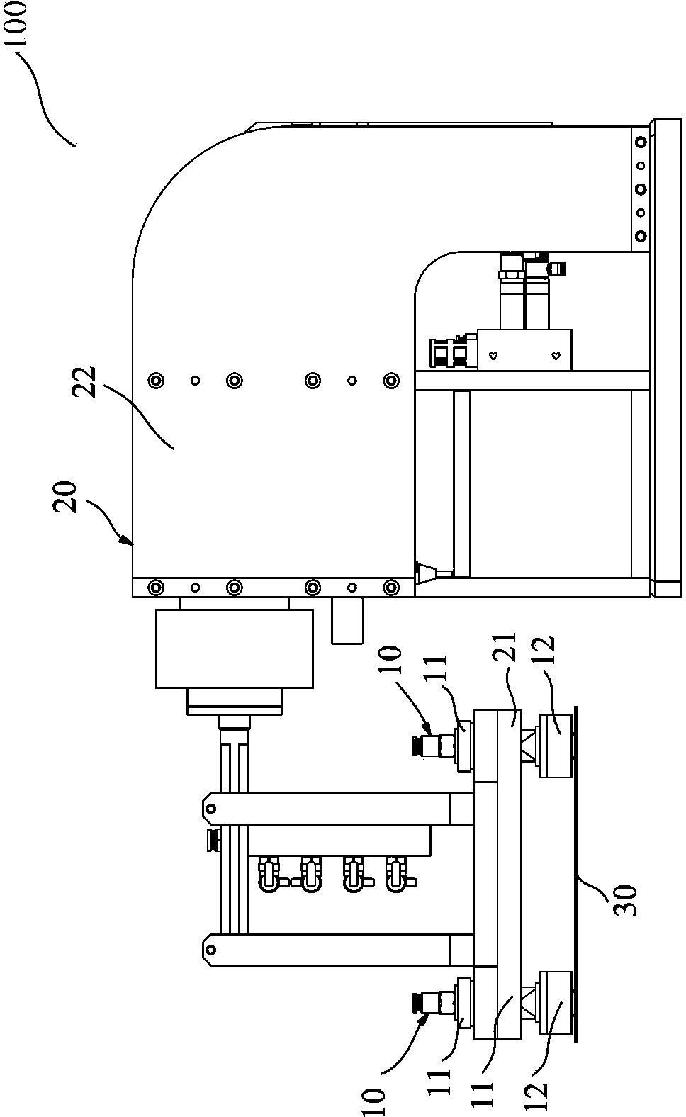
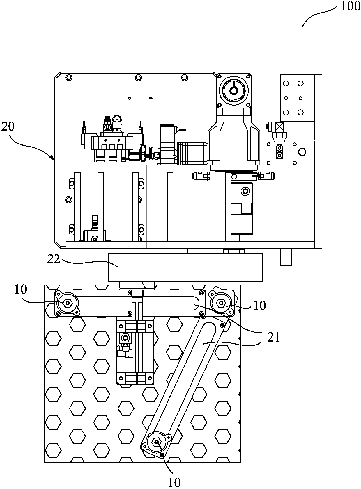
[0038] Please refer to the present invention figure 1 and figure 2 , is a schematic structural view of the bracket-type vacuum adsorption device of the present invention, as shown in the figure:

[0039] The present invention provides a stand-type vacuum adsorption device 100 , which mainly includes a moving device 20 and at least two vacuum suction cups 10 disposed on the moving device 20 . The moving device 20 includes at least one cross arm 21 and a carrier 22 connected to the cross arm 21 for operating the cross arm 21 to move. In this embod...


PUM


Abstract

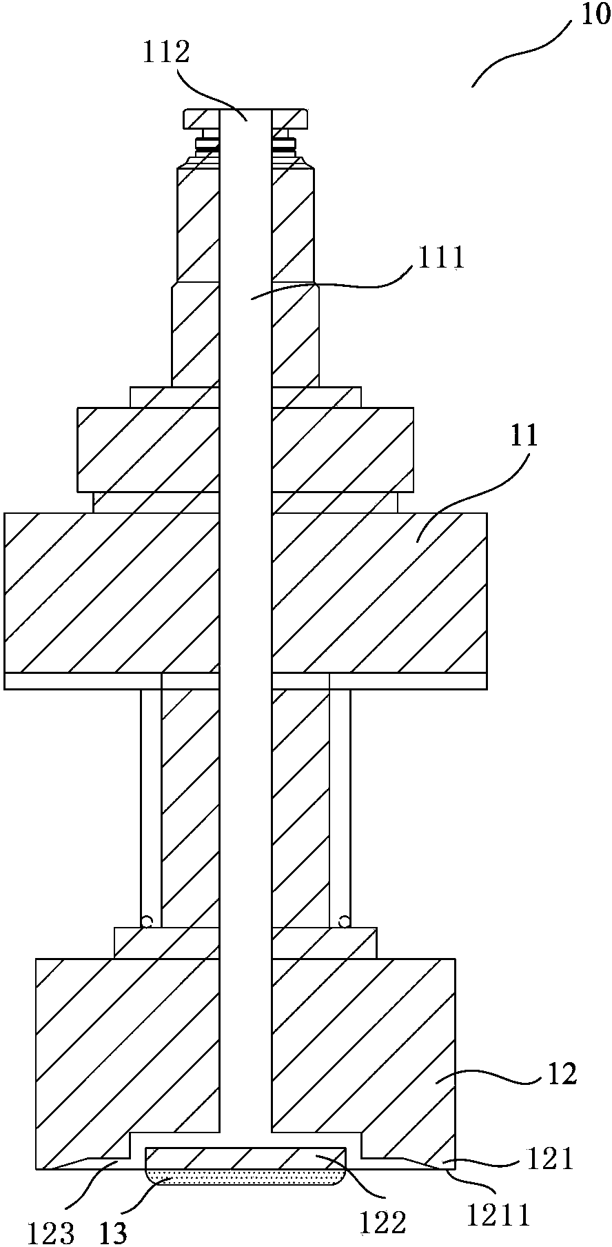
The invention provides a vacuum chuck and bracket type vacuum adsorption equipment provided with the vacuum chuck. The vacuum chuck is used for adsorbing at least one workpiece and comprises a chuck body with a gas inlet channel, a suction nozzle arranged on one side of the chuck body, and at least one friction gasket arranged on the bottom side of the suction nozzle, wherein the suction nozzle comprises an outer ring part and an inner ring part which are arranged on the bottom side of the suction nozzle; an annular gas gap which is gradually reduced in a direction from the bottom side of the suction nozzle to the gas inlet channel and is communicated with the gas inlet channel is arranged between the outer ring part and the inner ring part; when gas is blown out from the gas inlet channel to the annular gas gap to form an annular vacuum region for adsorbing the workpiece. When the workpiece is adsorbed by the annular vacuum region, the workpiece leans against the friction gaskets so that the disadvantages that the position of the suction nozzle needs to be adjusted additionally and a transportation and loading procedure can be carried out only when a framework fixes a side edge when the vacuum chuck is used for adsorbing the workpiece can be improved.

Description

technical field [0001] The present invention relates to a vacuum suction cup, especially a vacuum suction cup which can be used to absorb porous materials and increase the stability of the suction of the materials by means of friction pads, and also relates to a vacuum suction cup equipped with the vacuum suction cup Vacuum adsorption equipment. Background technique [0002] The prior art about vacuum chucks can be mainly divided into two types: one is a contact vacuum chuck, and the other is a non-contact vacuum chuck. [0003] Generally speaking, the more common and widely used technology is the contact vacuum chuck technology. Its principle is to directly apply the negative pressure generated by the flow of gas from the inlet to the outlet to the workpiece to be adsorbed. To achieve the purpose of absorbing the workpiece. Since the negative pressure is directly applied to the workpiece, when the workpiece is adsorbed on the suction cup, a vacuum-like environment can be ...

Claims


Application Information

Patent Timeline
Patent Type & Authority Applications(China)
IPC IPC(8): B25J15/06
Inventor 王人杰
Owner UTECHZONE CO LTD
Learn More