Threaded expansion cover

A technology of expansion sleeve and thread, which is applied in the field of expansion sleeve, can solve problems such as valve stem and push rod displacement, and achieve the effect of ensuring work stability

Inactive Publication Date: 2014-12-03
CHONGQING CHUANWU INSTR
View PDF0 Cites 0 Cited by
  • Summary
  • Abstract
  • Description
  • Claims
  • Application Information

AI Technical Summary

Problems solved by technology

[0003] The present invention intends to provide a threaded expansion sleeve to solve the disadvantage of easy displacement of the valve stem a

Method used


Image

  • Threaded expansion cover

Examples


Example Embodiment

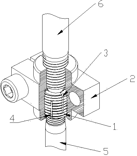
[0011] The reference signs in the drawings of the specification include: expansion sleeve body 1, opening and closing nut 2, upper expansion joint 3, lower expansion joint 4, valve stem 5, and push rod 6.

[0012] The present invention will be further described in detail below in conjunction with the drawings and specific embodiments:

[0013] according to figure 1 As shown, the threaded expansion sleeve in the embodiment of the present invention includes an expansion sleeve body 1, an outer thread is provided on the outer wall of the expansion sleeve body 1, and an inner thread (not shown in the figure) is provided on the inner wall of the expansion sleeve body 1, When in use, according to the specific models of the valve stem 5 and the actuator stem 6, the threaded expansion sleeve can be connected to the valve stem 5 or the push rod 6. In this embodiment, the internal thread of the threaded expansion sleeve and the valve stem 5 are preferably connected. External thread connecti...


PUM


Abstract

The invention discloses a threaded expansion cover including an expansion cover body, wherein an external thread is formed on the outer wall of the expansion cover body, an internal thread is formed on the inner wall of the expansion cover body, a plurality of expansion seams are formed on the expansion cover body, and the direction of the expansion seams is parallel to the axis of the expansion cover body or at an acute angle to the axis of the expansion cover body. The threaded expansion cover adopting the scheme provided by the invention is simple in structure and excellent in practicality.

Description

technical field [0001] The invention relates to an expansion sleeve, in particular to an expansion sleeve with internal and external threads. Background technique [0002] The opening or closing of the sliding plate control valve requires an actuator to provide power to the valve stem. The actuator usually uses a cylinder or a hydraulic cylinder. When in use, the valve stem needs to be connected to the push rod of the actuator, and the push rod refers to the piston rod of the air cylinder or hydraulic cylinder. Usually the actuator push rod and the end of the valve stem have external threads, and the two are connected by a split nut with internal threads, and the split nut is clamped on the valve stem and the push rod. When installing and connecting, the sliding plate control valve needs to be fixed, so the push rod must be axially limited, and the split nut is installed on the valve rod before screwing in the push rod. However, due to the limitation of machining accuracy, ...

Claims


Application Information

Patent Timeline
IPC IPC(8): F16K31/44F16K31/12
CPCF16K31/12F16B7/182
Inventor 蔡杰浩
Owner CHONGQING CHUANWU INSTR
Why Eureka
Try Eureka