Series-parallel connection centrifugal pump

A centrifugal pump and parallel technology, applied in the field of centrifugal pumps, can solve problems such as large workload, uncontrollable work, leakage, etc., and achieve the effect of improving service life, physical sealing performance and controllability

Active Publication Date: 2014-07-02
合肥华升泵阀股份有限公司
View PDF5 Cites 13 Cited by
  • Summary
  • Abstract
  • Description
  • Claims
  • Application Information

AI Technical Summary

Problems solved by technology

However, the current one-way valve structure applied to the above-mentioned centrifugal pump is affected by its use environment and its performance. Realize its airtight performance; on the one hand, in order to ensure the opening and closing sensitivity of the one-way valve, the rubber pad is usually loosely fixed on the closing surface of the plate body, so as to ensure that the liquid medium can be filled "quickly" when the water pressure impacts The gap between the rubber pad and the plate body generates water thrust to close the flow channel; however, the actual working environment of the check valve itself often needs to realize its frequent opening and closing, and the check valve plate body frequently hits the flow channel for a long time When it is opened and closed, the soft rubber pad is easily damaged, torn or even falls off by itself, which will cause leakage problems and affect the actual use efficiency of the pump. This is also the main reason for its short service life and frequent maintenance; On the

Method used


Image

  • Series-parallel connection centrifugal pump
  • Series-parallel connection centrifugal pump
  • Series-parallel connection centrifugal pump

Examples


Example Embodiment

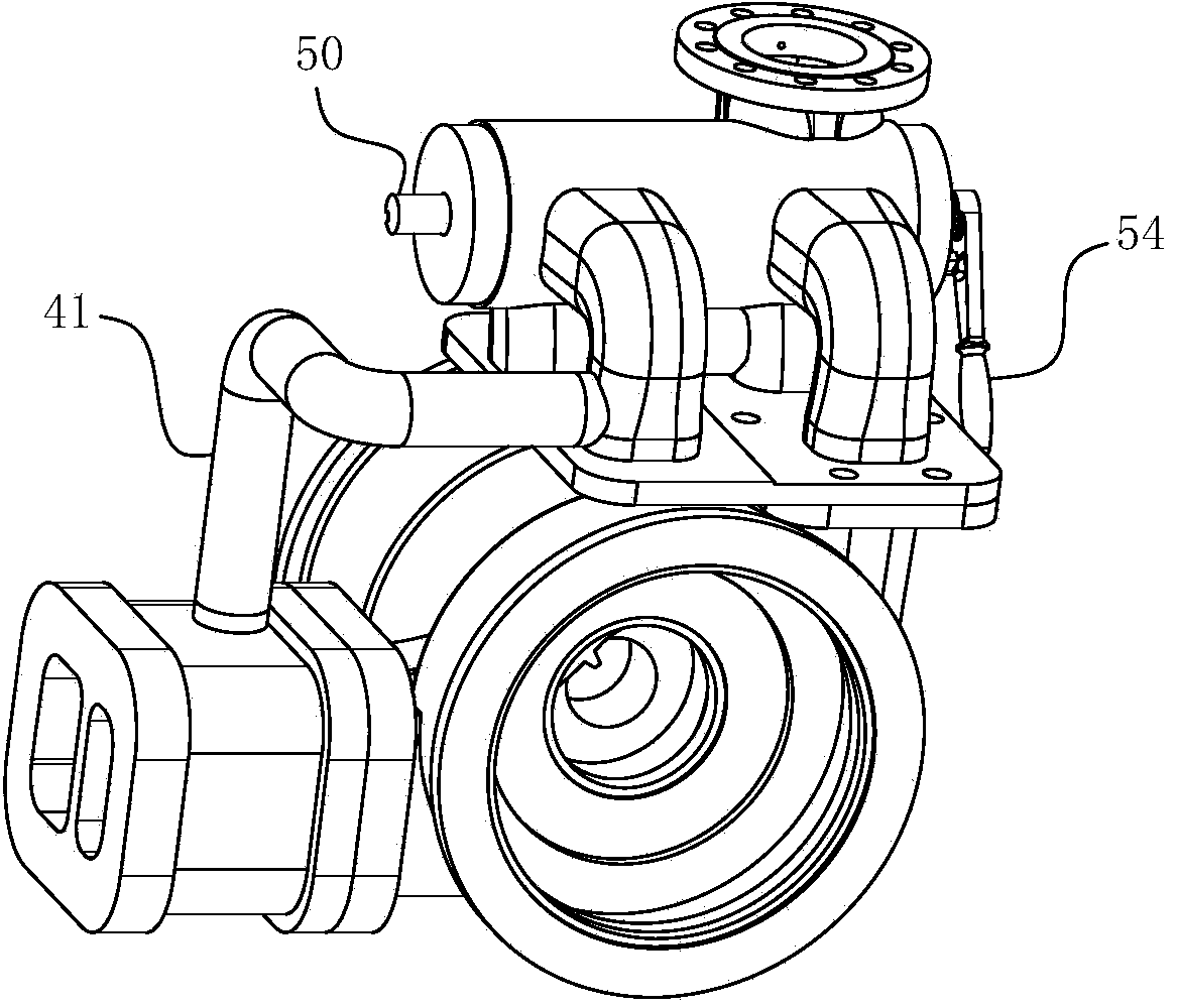
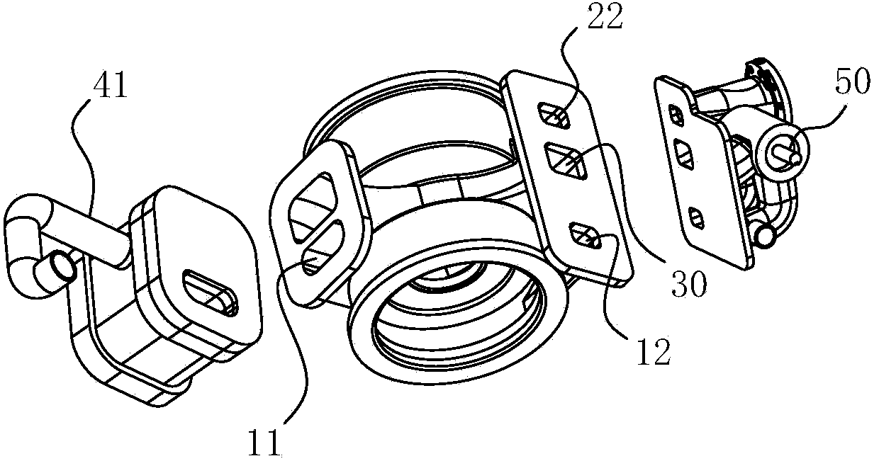
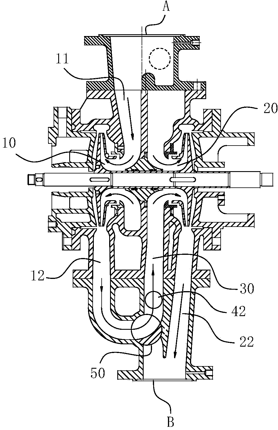
[0040] For ease of understanding, combine here Figure 1-13 The specific components and workflow of the present invention are described as follows:

[0041] The present invention adopts such as Figure 1-13 The shown rotary valve body structure realizes the operation purpose of "one valve and two controls". In actual use, the rotation angles of the first spool section 51 and the second spool section 52 are controlled at the same time by operating the rotating handle, thereby starting To the purpose of series and parallel operation relative to the pump body; in this way, on the one hand, the part of the switch part that cannot be directly manually controlled is controlled by the spool of the same control switch assembly, which has stronger controllability, stability and reliability. The performance can be greatly guaranteed, and at the same time, it will have a beneficial effect on its actual service life; on the other hand, the relative position of each flow channel is arranged in...


PUM


Abstract

The invention belongs to the field of centrifugal pumps and particularly relates to a series-parallel connection centrifugal pump which has the flow channel series-parallel connection switching capacity. The series-parallel connection centrifugal pump comprises a pump body and a pump shaft. The pump shaft is provided with two impeller parts, and a first cavity channel and a second cavity channel are formed in a pump cavity corresponding to the two impeller parts. A first bypass flow channel, a second bypass flow channel, a first liquid outlet flow channel and a second liquid outlet flow channel are formed in the pump body, wherein the first bypass flow channel and the second bypass flow channel are used for communicating an outlet of an external liquid inlet pipeline and an inlet of the first cavity channel as well as the outlet of the external liquid inlet pipeline and an inlet of the second cavity channel respectively, and the first liquid outlet flow channel and the second liquid outlet flow channel are used for communicating an inlet of the external liquid outlet pipeline and an outlet of the first cavity channel as well as the inlet of the external liquid outlet pipeline and an outlet of the second cavity channel. A branch flow channel is further arranged in the pump cavity, one end of the branch flow channel is communicated with a liquid inlet of the second cavity channel, and the other end of the branch flow channel is communicated with the first liquid outlet flow channel to form a three-way joint. The series-parallel connection centrifugal pump further comprises a switching part, a switching assembly is arranged at the second liquid outlet flow channel, and the switching assembly and the switching part are in electric linkage or mechanical linkage. Due to the linkage structure, the series-parallel connection centrifugal pump is reasonable and practical in structure, long in service life and reliable and stable in work.

Description

technical field [0001] The invention belongs to the field of centrifugal pumps, and in particular relates to a series-parallel centrifugal pump capable of switching flow passages between series and parallel. Background technique [0002] Series-parallel centrifugal pumps are one of many types of centrifugal pumps, and are widely used in fields such as fire protection and ships. The original intention of using series-parallel centrifugal pumps is to solve the technical problems of short head and small flow of traditional centrifugal pumps in the past; through the pre-divided flow channels inside the pump body, the coordinated flow distribution of the one-way valve and the rotary switch valve is realized. Its series and parallel function. However, the current one-way valve structure applied to the above-mentioned centrifugal pump is affected by its use environment and its performance. Realize its airtight performance; on the one hand, in order to ensure the opening and closi...

Claims


Application Information

Patent Timeline
IPC IPC(8): F04D13/14F04D15/00F04D29/00
CPCF04D1/10
Inventor 柴立平胡敬宁张军辉李强陈先春李跃何玉杰
Owner 合肥华升泵阀股份有限公司
Why Eureka
Try Eureka