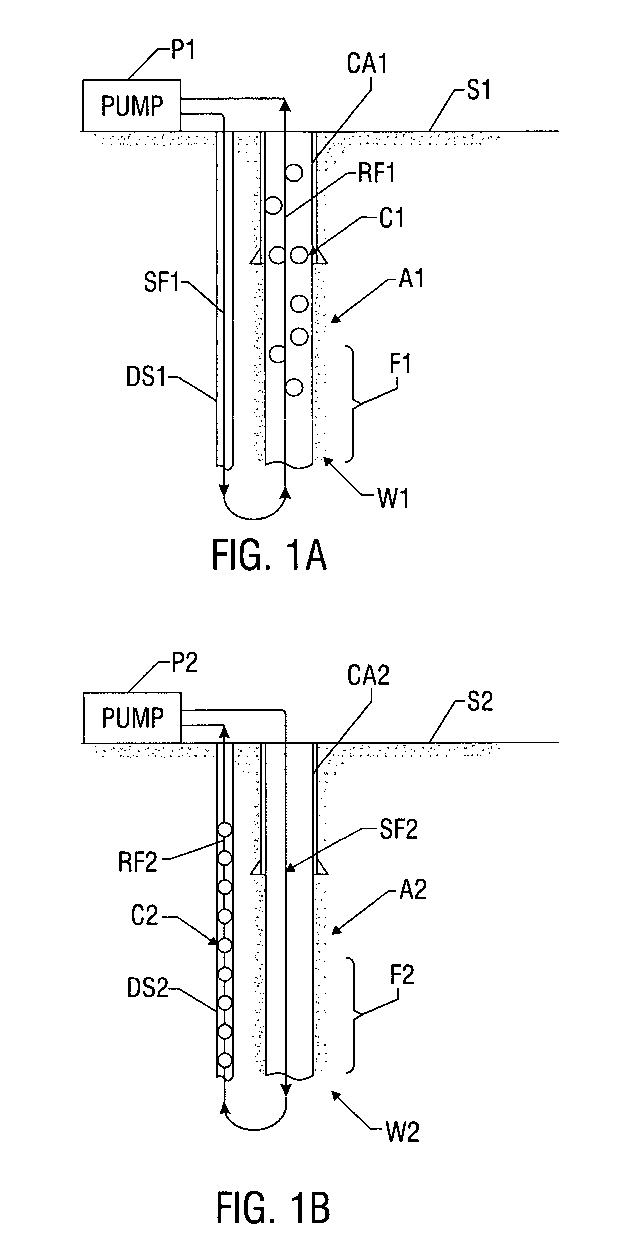
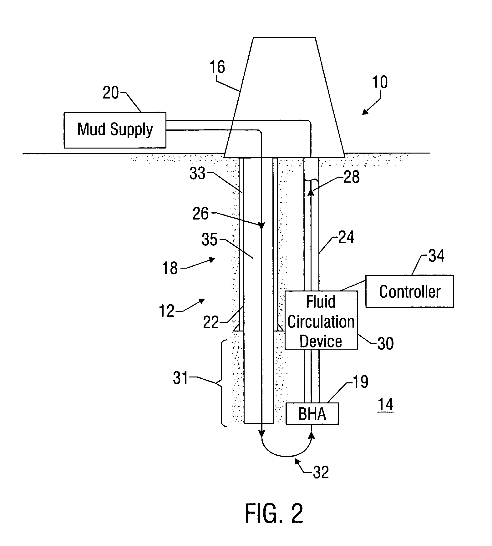
[0010]The present invention provides wellbore systems for performing downhole wellbore operations for both land and offshore wellbores. Such drilling systems include a rig that moves an umbilical (e.g., drill string) into and out of the wellbore. A bottomhole assembly, carrying the drill bit, is attached to the bottom end of the drill string. A well control assembly or equipment on the wellhead receives the bottomhole assembly and the umbilical. A drilling fluid system supplies a drilling fluid via a fluid circulation system having a supply line and a return line. During operation, drilling fluid is fed into the supply line, which can include an annulus formed between the umbilical and the wellbore wall. This fluid washes and lubricates the drill bit and returns to the well control equipment carrying the drill cuttings via the return line, which can include the umbilical.
[0011]In one embodiment of the present invention, a fluid circulation device, such as a positive displacement or centrifugal pump, positioned along the return line provides the primary motive force for circulating the drilling fluid through the supply line and return line of the fluid circulation system. By “primary motive force,” it is meant that operation of the fluid circulation device provides the majority of the force or differential pressure required to circulate drilling fluid through the supply line and return line. In a separate arrangement, one or more supplemental fluid circulation devices are coupled to the supply line and / or return line to assist in circulating drilling fluid. By “supplemental,” it is meant that these additional fluid circulation devices are task-specific (e.g., providing zones of higher or lower fluid pressure / flow rates, improve bit cleaning, and / or overcoming circulation losses in specific segments of the fluid circulation system), but primarily operate in cooperation with the fluid circulation device. The fluid circulation device can be any device adapted to actively induce flow or controlled movement of a fluid body or column. Such devices can include centrifugal pumps, positive displacement pumps, piston-type pumps, jet pumps, magneto-hydrodynamic drives, and other like devices. In one embodiment of the present invention, the operation of the fluid circulation device is generally independent of the operation of the drill bit. For instance, the flow rate or pressure differential provided by the fluid circulation device can be controlled without necessarily adjusting the rotational speed of the drill bit or the driver (e.g., rotating drill string) rotating the drill bit. A controller in the system may be utilized to control the operation of the fluid circulation device according to programmed instructions and / or in response to a parameter of interest, which may be pressure, fluid flow, a characteristic of the wellbore fluid or the formation of any other suitable downhole or surface measured parameter.
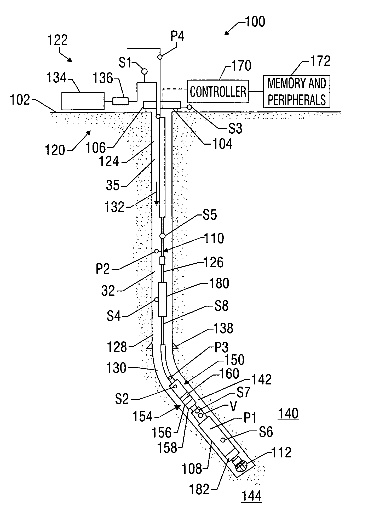
[0012]The system also includes downhole devices for performing a variety of functions. Exemplary downhole devices include devices that control the drilling fluid flow rate and flow paths. For example, the system can include one or more flow-control devices that can stop the flow of the fluid in the umbilical and / or the annulus. Such flow-control devices can be configured to direct fluid from the annulus into the umbilical. Another exemplary downhole device can be configured for processing the cuttings (e.g., reduction of cutting size) and other debris flowing in the return line. For example, a comminution device can be disposed in the return line upstream of the fluid circulation device.
[0013]In one embodiment, sensors communicate with a controller via a telemetry system control the drilling activity according to one or more parameters (e.g., a specified range of the wellbore pressure at a zone of interest or specified rate of penetration). The sensors are strategically positioned throughout the system to provide information or data relating to one or more selected parameters of interest such as drilling parameters, drilling assembly or BHA parameters, and formation or formation evaluation parameters. The controller suitable for drilling operations can include programs for maintaining drilling activity within the specified parameter or parameters. The controller may be programmed to activate downhole devices according to programmed instructions or upon the occurrence of a particular condition.
[0014]In one embodiment, a well bore assembly utilizing a bit rotated by a downhole motor and a fluid circulation device driven by an associated motor. A power transmission line or conduit supplies power to the each of the motors. Additionally, the wellbore assembly can includes a controller coupled to sensors configured to measure one or more parameters of interest (e.g., pressure of the supply fluid). In one arrangement, the motors are variable speed electric motors that are adapted for use in a wellbore environment. Other embodiments of motors can be operated by pressurized gas, hydraulic fluid, and other energy streams supplied from a surface location. Other equally suitable arrangements can include a single motor (electric or otherwise) that drives both the bit and the fluid circulation device. In another embodiment, the wellbore system includes a downhole power unit for energizing one or more of the motors. The stored energy supply, in certain embodiments, is replenished from a surface source. Further, a plurality of fluid circulation devices can be positioned serially or in parallel along the return line.
[0015]Examples of the more important features of the invention have been summarized (albeit rather broadly) in order that the detailed description thereof that follows may be better understood and in order that the contributions they represent to the art may be appreciated. There are, of course, additional features of the invention that will be described hereinafter and which will form the subject of the claims appended hereto.

