Speed control for a pumping system

a technology of speed control and pumping system, which is applied in the direction of pump control, positive displacement liquid engine, non-positive displacement fluid engine, etc., can solve the problems of increasing current and power drawn, centrifugal pump does not lend itself to higher head applications, etc., and achieves the effect of reducing the load of the pump

Inactive Publication Date: 2003-07-24
F E MEYERS
View PDF0 Cites 82 Cited by
  • Summary
  • Abstract
  • Description
  • Claims
  • Application Information

AI Technical Summary

Problems solved by technology

Therefore, the centrifugal pump does not lend itself to higher head applications.
This results in increased current and power being drawn by the centrifugal pumping system.

Method used


Image

  • Speed control for a pumping system
  • Speed control for a pumping system
  • Speed control for a pumping system

Examples


Embodiment Construction

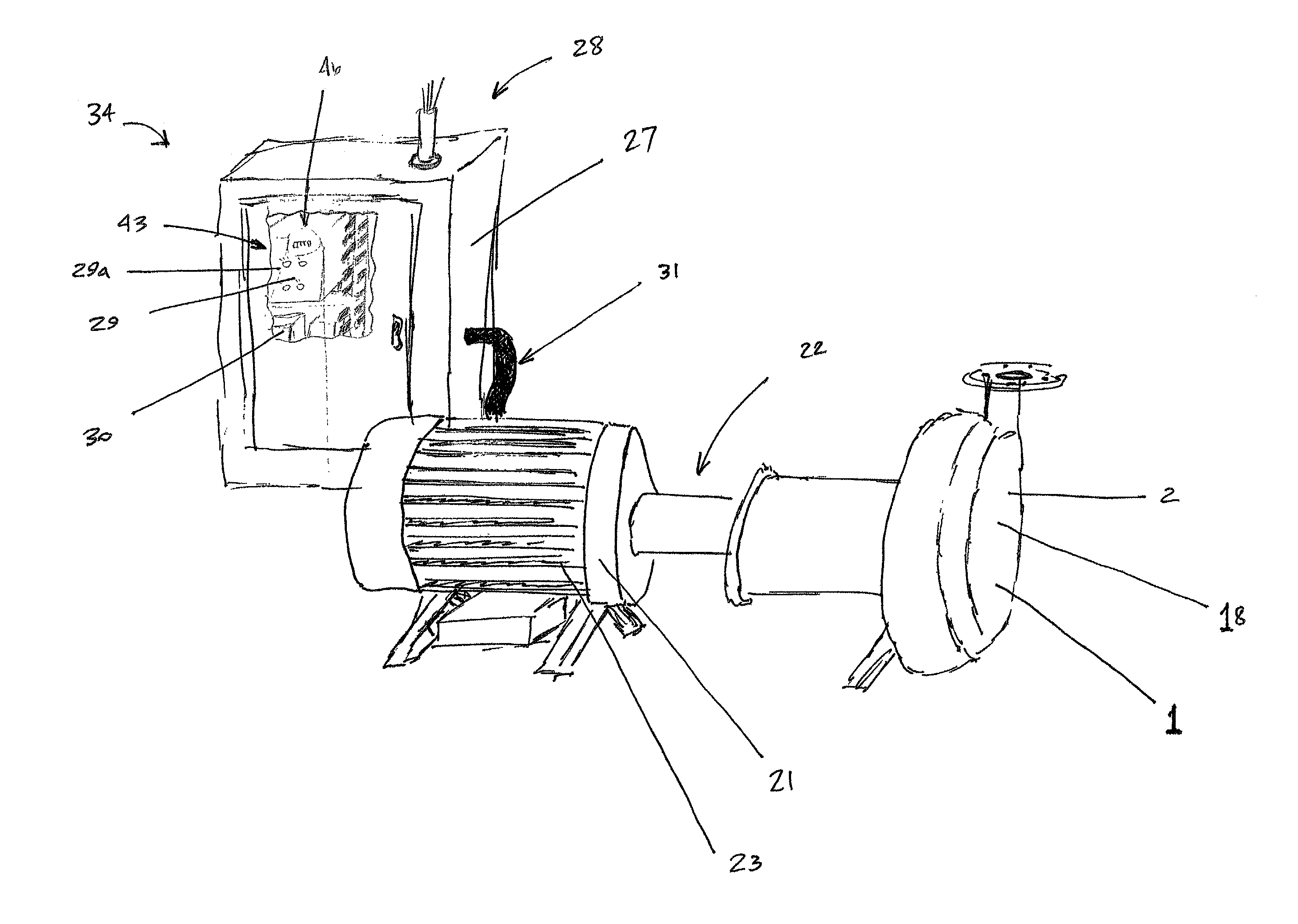
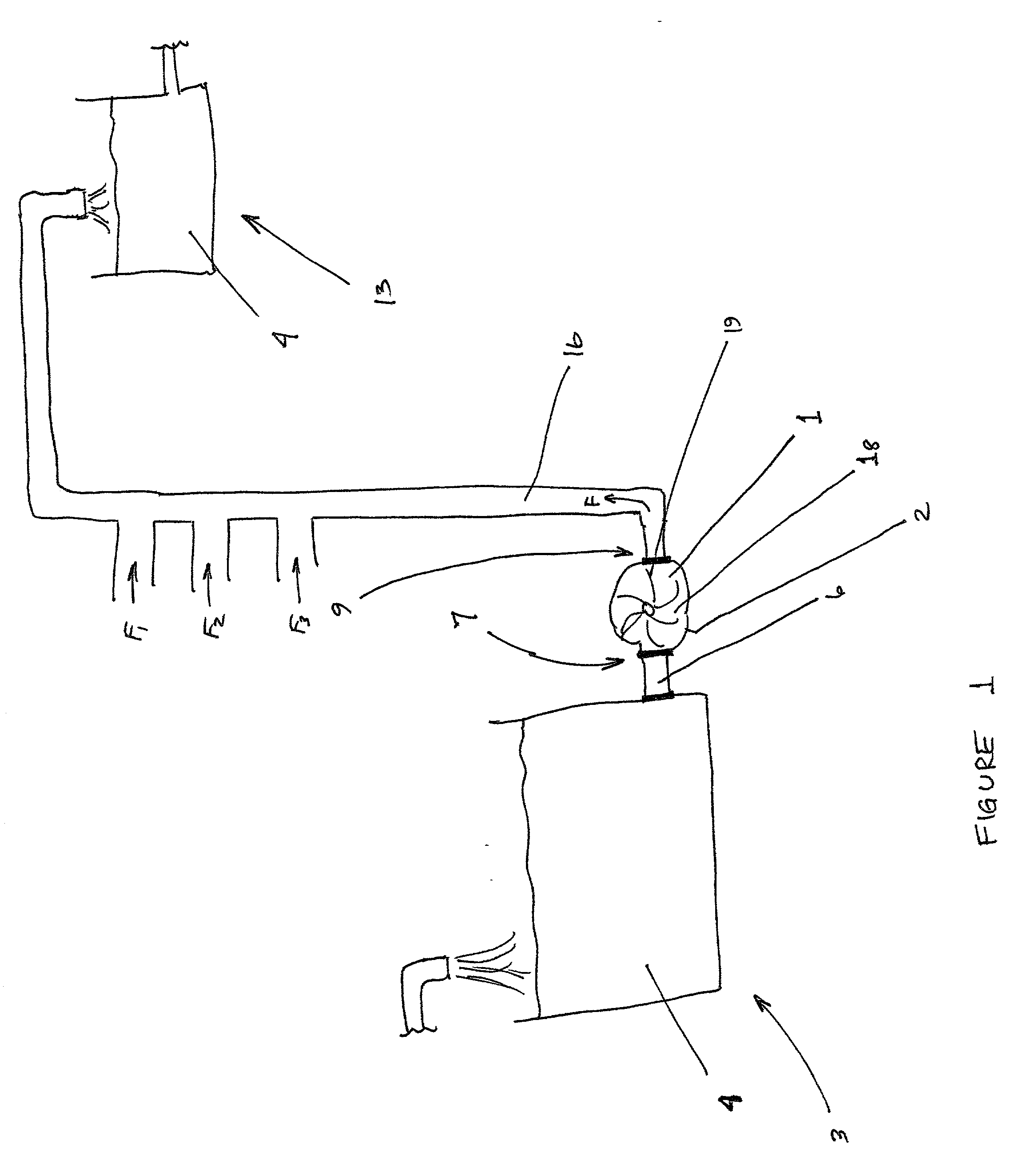
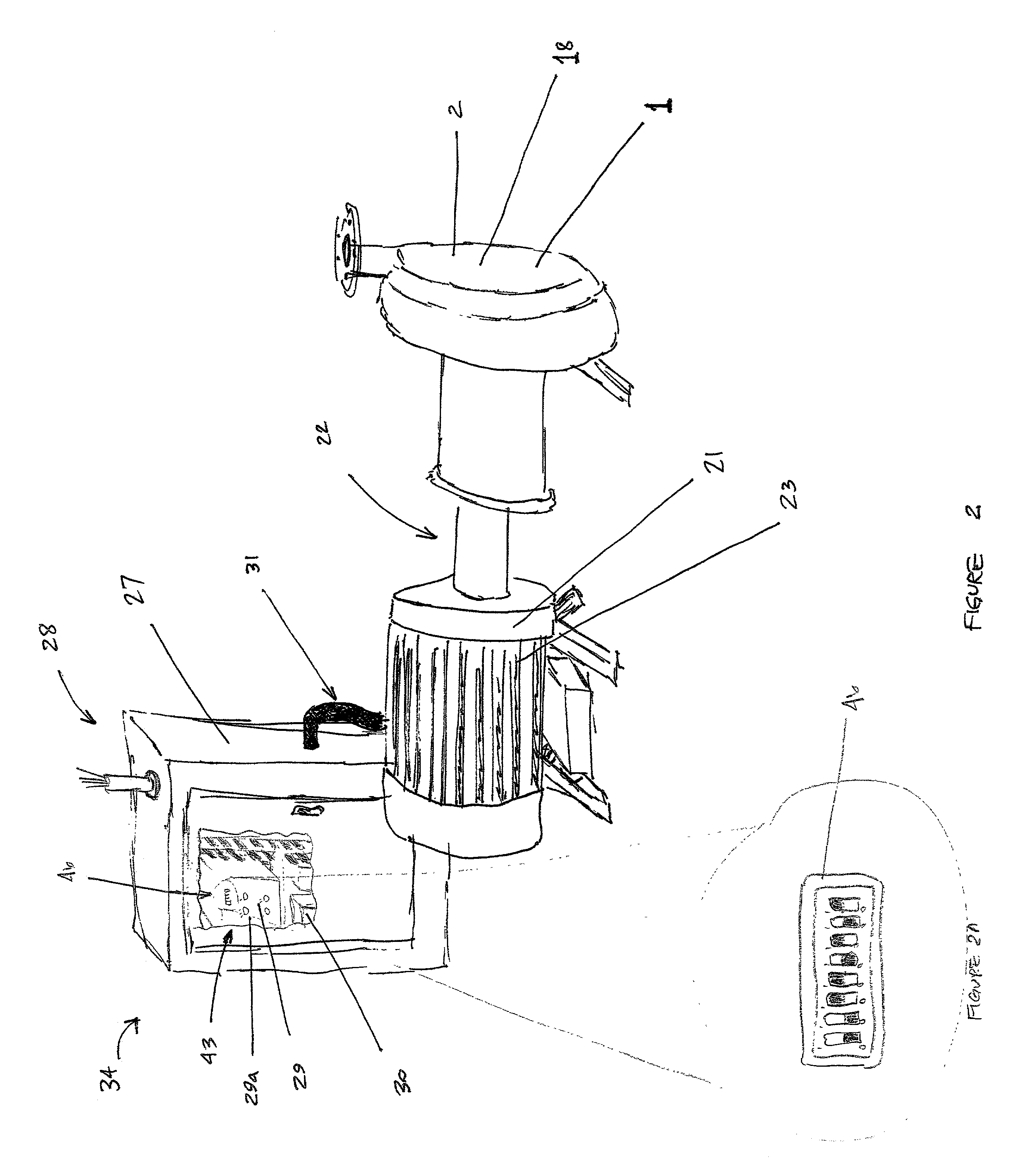
[0019] Referring now to the drawings wherein the showings are for purposes of illustrating a preferred embodiment of the invention only and not for purposes of limiting the same, FIG. 1 depicts a schematic representation of a wastewater pump 1 operatively connected to a supply source 3 of slurry mixture 4 via a slurry inlet conduit 6. The wastewater pump 1 may include an inlet 7 for use in receiving the slurry mixture 4 from the slurry conduit 6. The wastewater pump 1 may also include an impeller 19, shown in FIG. 6, for use in pumping the slurry mixture 4 via an outlet 9 to a discharge tank 13 or other storage means. In this manner, the slurry mixture 4 is transmitted through the body 2 of the pump 1. The outlet 9 of the wastewater pump 1 may be connected to the discharge tank 13 via slurry outlet conduit 16. It is noted that any configuration of supply source and discharge tank storage means for containing the slurry mixture may be chosen with sound engineering as is appropriate f...


PUM


Abstract

A wastewater pumping system includes a centrifugal pump operatively connected to an electric motor via a coupling. The speed of the electric motor is automatically varied responsive to the head or load realized by the pump of the system as it varies with the composition of the slurry mixture. A variable frequency drive is operatively connected to the motor and the electrical power supply that affects a shift or change in electrical frequency delivered to the electrical motor so that the speed of the motor and consequently the pump is varied. This allows the electrical power deliver to the system to remain substantially unchanged for varying loads realized by the pump.

Description

I. BACKGROUND OF THE INVENTION[0001] A. Field of Invention[0002] The present invention relates to the art of wastewater pumps and more specifically to a speed control device for operating the wastewater pumps.[0003] B. Description of the Related Art[0004] Wastewater pumping systems are known to use centrifugal pumps. Centrifugal pumps work well to maintain flow rate. However, when pressure or head is increased in a wastewater system the flow rate decreases. Therefore, the centrifugal pump does not lend itself to higher head applications.[0005] A typical centrifugal pump functions based on speed of the impeller or kinetic energy of the fluid being pumped based on the impeller speed. This is contrasted with positive displacement pumps, such as piston pumps or the like. Typically, the centrifugal pump is powered by an electric motor. That is to say that the motor, generally an AC motor, rotates the impeller of the pump at a specific speed based upon the operating characteristics of the...

Claims


Application Information

Patent Timeline
Patent Type & Authority Applications(United States)
IPC IPC(8): F04B49/20F04D15/00
CPCF04D15/0066F04B49/20
Inventor JONES, ROBERTGIBSON, JULIECHANDLER, WILLIAM
Owner F E MEYERS
Why Eureka
Try Eureka