Centrifugal pump

a centrifugal pump and centrifugal pump technology, applied in the field of centrifugal pumps, can solve the problems of marginally impairing the overall appearance of the centrifugal pump, and achieve the effect of universal applicability and good leakage tightness

Active Publication Date: 2008-02-07
BUHLER MOTOR GMBH
View PDF3 Cites 84 Cited by
  • Summary
  • Abstract
  • Description
  • Claims
  • Application Information

AI Technical Summary

Benefits of technology

[0005] It is therefore the object of the present invention to provide a centrifugal pump, in which very good leak tightness is achieved with a minimum number of parts, minimum weight and minimum assembly costs with universal applicability without impairing the overall visual appearance of the centrifugal pump.

Problems solved by technology

Since the second housing part takes up the smallest portion of the visible housing surface in the generic pump type, this housing part is made of a material that is permeable to laser light, thereby only marginally impairing the visual overall impression of the centrifugal pump.

Method used


Image

  • Centrifugal pump
  • Centrifugal pump
  • Centrifugal pump

Examples


Embodiment Construction

[0024] In describing preferred embodiments of the present invention illustrated in the drawings, specific terminology is employed for the sake of clarity. However, the invention is not intended to be limited to the specific terminology so selected, and it is to be understood that each specific element includes all technical equivalents that operate in a similar manner to accomplish a similar purpose.

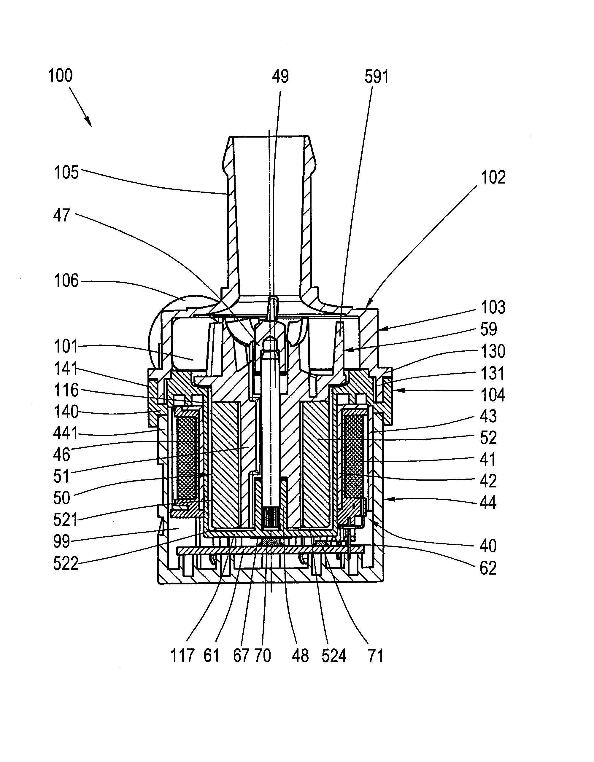
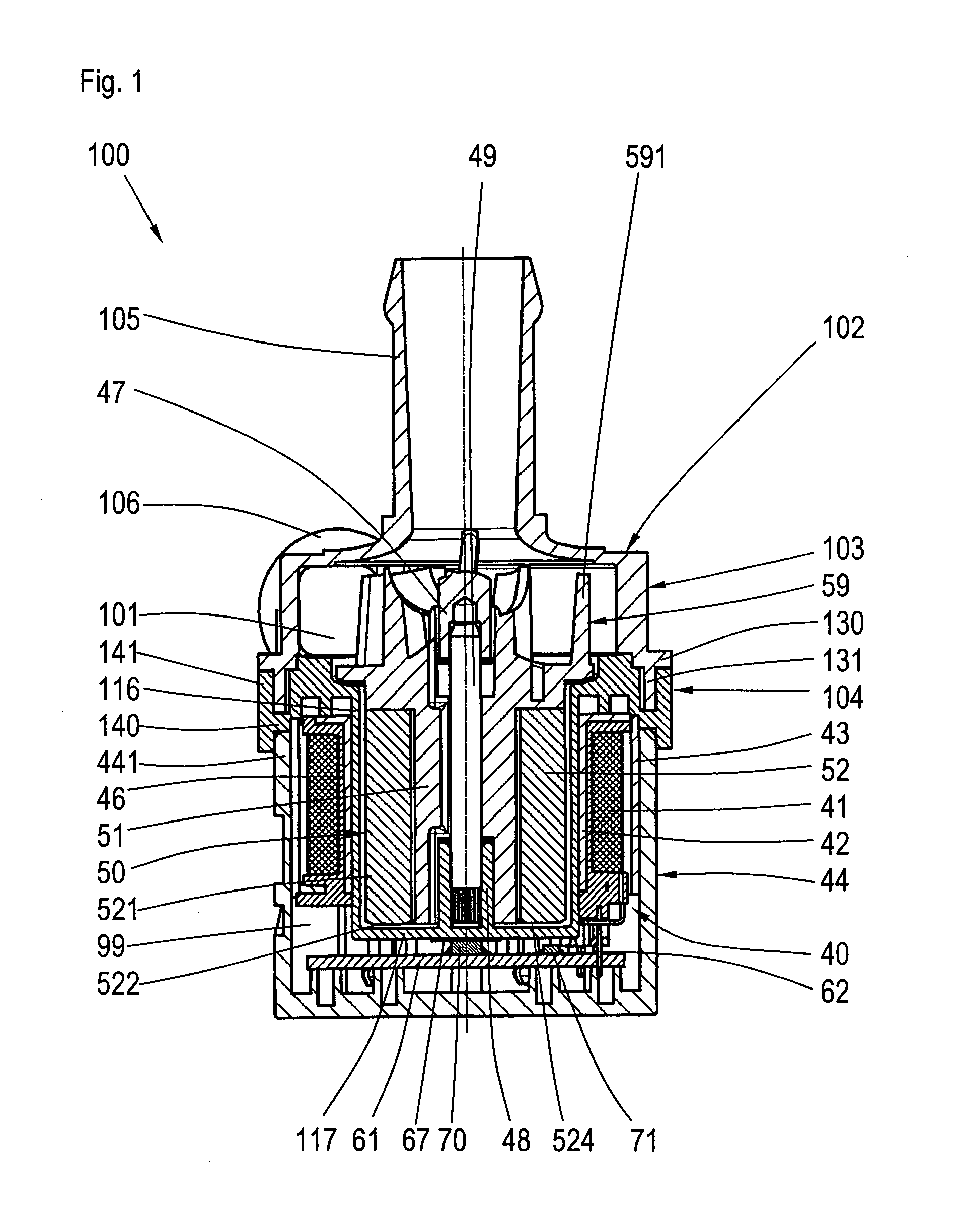
[0025]FIG. 1 shows a sectional view of the inventive centrifugal pump 100, with a pump housing 102 comprising a first housing part 103 and a second housing part 104 attached thereto. A motor housing part 44 delimits a dry chamber, which is filled out by a stator 40 of an electronically commutated direct current motor and its control electronic system. The motor housing part 44 is attached to the second housing part 104. The first and the second housing parts 103, 104 delimit a wet chamber 101 of the centrifugal pump. The second housing part 104 is designed as a single piece with a conta...


PUM

PropertyMeasurementUnit
wavelengthaaaaaaaaaa
sealing areaaaaaaaaaaa
areaaaaaaaaaaa

Abstract

The invention relates to a centrifugal pump comprising a pump housing made of injection-molded plastics with a first housing part, which is designed as a single piece with a suction connection and a pressure connection, and comprises a sealing area, by means of which said first housing part is joined in a liquid-tight manner to a second housing part, that receives an electric motor, and a motor housing part. It is the object of the present invention to provide a centrifugal pump, in which very good leak tightness is achieved with minimum number of parts, minimum weight and minimum assembly costs with universal applicability without impairing the visual overall impression of the centrifugal pump. This objective is achieved according to the invention in that the second housing part is made of a material that is permeable to laser light of a wavelength or a wavelength range, and the first housing part is made of a material that absorbs the same laser light, and the first housing part and the second housing part are heat-sealed to one another.

Description

BACKGROUND OF THE INVENTION [0001] (1) Field of the Invention [0002] The invention relates to a centrifugal pump comprising a pump housing made of injection-molded plastics with a first housing part, which is designed as a single piece with a suction connection and a pressure connection, and comprises a sealing area, by means of which said first housing part is joined in a liquid-tight manner to a second housing part, which receives an electric motor, and a motor housing part [0003] (2) Description of Related Art [0004] A centrifugal pump of the generic type has been disclosed in U.S. Pat. No. 6,663,362 B1, in which pump a sealing ring has to be inserted for the purpose of sealing that pump room of the centrifugal pump, through which liquid flows. No seal is mentioned for the motor housing part. Furthermore, screws are provided with the help of which the housing parts are joined to one another. This known centrifugal pump comprises a large number of individual parts that have to be ...

Claims


Application Information

Patent Timeline
Patent Type & Authority Applications(United States)
IPC IPC(8): F04D13/02
CPCB29L2031/7496F04D29/026F04D29/426F04D29/628B29C65/1635B29C66/1222Y10T403/477B29C66/124B29C66/543B29C66/232B29C65/1667B29C65/1687Y10T29/49243B29C66/1224B29C66/73921F05D2300/43F05D2230/234F05D2300/52F04D13/0626
Inventor IHLE, OLAIPETERREINS, THOMASSCHMIDT, HELMUTSUTTNER-REIMANN, ARMIN
Owner BUHLER MOTOR GMBH
Why Eureka
Try Eureka