Riserless recirculation/transfer pump and mixer/pre-melter for molten metal applications

a recirculating/transfer pump and mixer/pre-melter technology, which is applied in the direction of machines/engines, stators, liquid fuel engines, etc., can solve the problems of clogging the relative narrow riser tube b>11/b>, and prolonging the melt time. , to achieve the effect of reducing the number of components and reducing the complexity of the pump system

Active Publication Date: 2012-06-28
MORANDO JORGE A
View PDF5 Cites 75 Cited by
  • Summary
  • Abstract
  • Description
  • Claims
  • Application Information

AI Technical Summary

Benefits of technology

[0017]It is an advantage of the present invention to provide a pump which creates a forced, highly forced or super forced vortex of molten metal within a generally vertical tube body of the pump to lift the whirling molten metal for transferring, mixing, and / or pre-melting applications.
[0018]It is another advantage of the present invention that the lifting cavity has a relatively large internal diameter allowing the inner walls to be readily accessed for cleaning and removal of accumulated metal and dross. Preferably, the vessel internal diameter being between 1.5 to 4 times the impeller outside diameter.
[0019]It is still another advantage of the present invention that two coaxial impellers are driven by a common drive motor-shaft design to simultaneously provide the lifting vortex flow and the recirculation flow. An upper impeller being mounted within the tubular lifting vortex cavity, while the lower impeller is mounted within a volute to recirculate a bath of molten metal.
[0020]It is still yet another advantage of the present invention that the lifting vortex cavity has a curved shape and size that complements the intended vortex formed therein. That is, in a transfer application, the lifting cavity has a particular curvature shape, while in a pre-melting / mixing application the lifting vortex cavity has at least a third degree curved shape as described above (e.g., has a pressure distribution following P / γ=C2r3 / 3g+h or P / γ=C2r4 / 4g+h).
[0021]An advantage of the present invention over prior art transfer-type pumps is that the present invention eliminates the support posts, riser tube, and one impeller bearing thereby reducing the complexity of the pump system and reducing the number of components subject to deterioration due to the molten metal environment and which must eventually be replaced.
[0022]It is an additional advantage of the present invention when mixing or pre-melting to provide an upper impeller having a plate with a plurality of radial vanes facing into the tubular body. When metal scrap chips are inserted into the pump's tubular cavity, the plurality of radial vanes on the upper impeller causes the metal chips to be directed radially outwardly into the pump-generated uplifting vortex of molten metal. The rotational velocity of the impeller causes the chips to further penetrate the surface of the vortex to fully immerse the chips within the molten metal.

Problems solved by technology

A well-known problem with previous transfer pumps, however, is that the relatively narrow riser tube 11 becomes clogged as small droplets of the molten metal accumulate in the riser each time the pump stops transferring and the metal stops flowing through the riser.
As a result of this problem, furnace operators must frequently replace the transfer pump's riser tube as they are too narrow to effectively clean.
These treatments have varying degrees of success, but still only delay the inevitable clogging of the riser.
The current process(es), however, is not effective to fully immerse the solid chips into the molten bath resulting in a longer melt time.
As will be discussed in greater detail below, these nearly free vortex-based systems do not provide sufficient residence times within the bath to efficiently melt and mix the newly deposited chips into the bath.
Consequently, any metal particles introduced therein will float at the top of the metal and exit without being melted at the top exit outlet, generating a large amount of dross instead of liquid metal.
The limited space available typically prevents furnace operators from having permanently installed transfer pumps and / or mixer / pre-melter systems within a furnace (in addition to the recirculation pump).
Another drawback of conventional molten metal pumps is the highly inefficient use of very large / high horsepower motors which are stepped down in velocity electronically with a frequency converter that maintains the torque constant, thus reducing the output horsepower when running the equipment at a safe RPM.

Method used


Image

  • Riserless recirculation/transfer pump and mixer/pre-melter for molten metal applications
  • Riserless recirculation/transfer pump and mixer/pre-melter for molten metal applications
  • Riserless recirculation/transfer pump and mixer/pre-melter for molten metal applications

Examples


Embodiment Construction

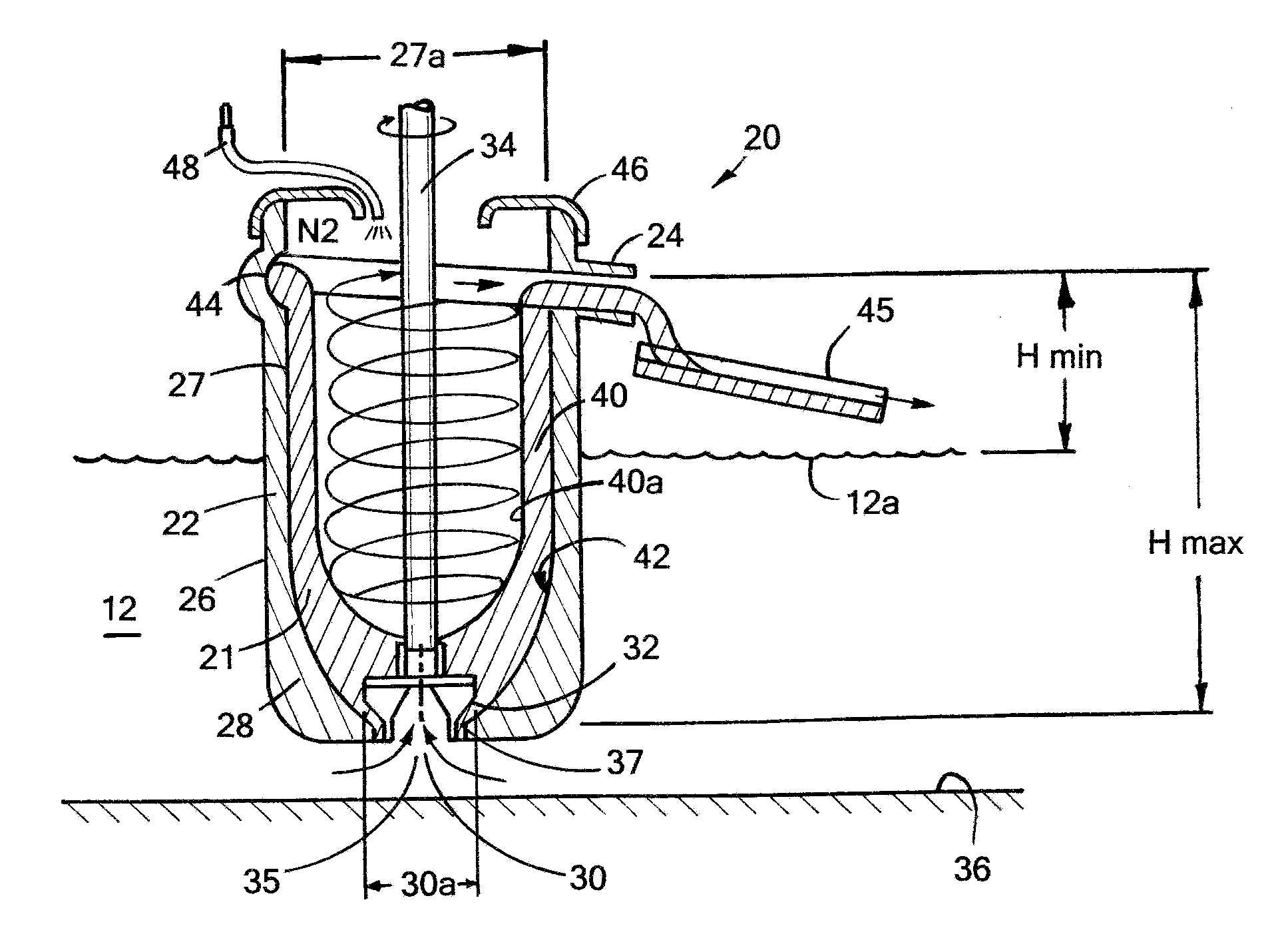
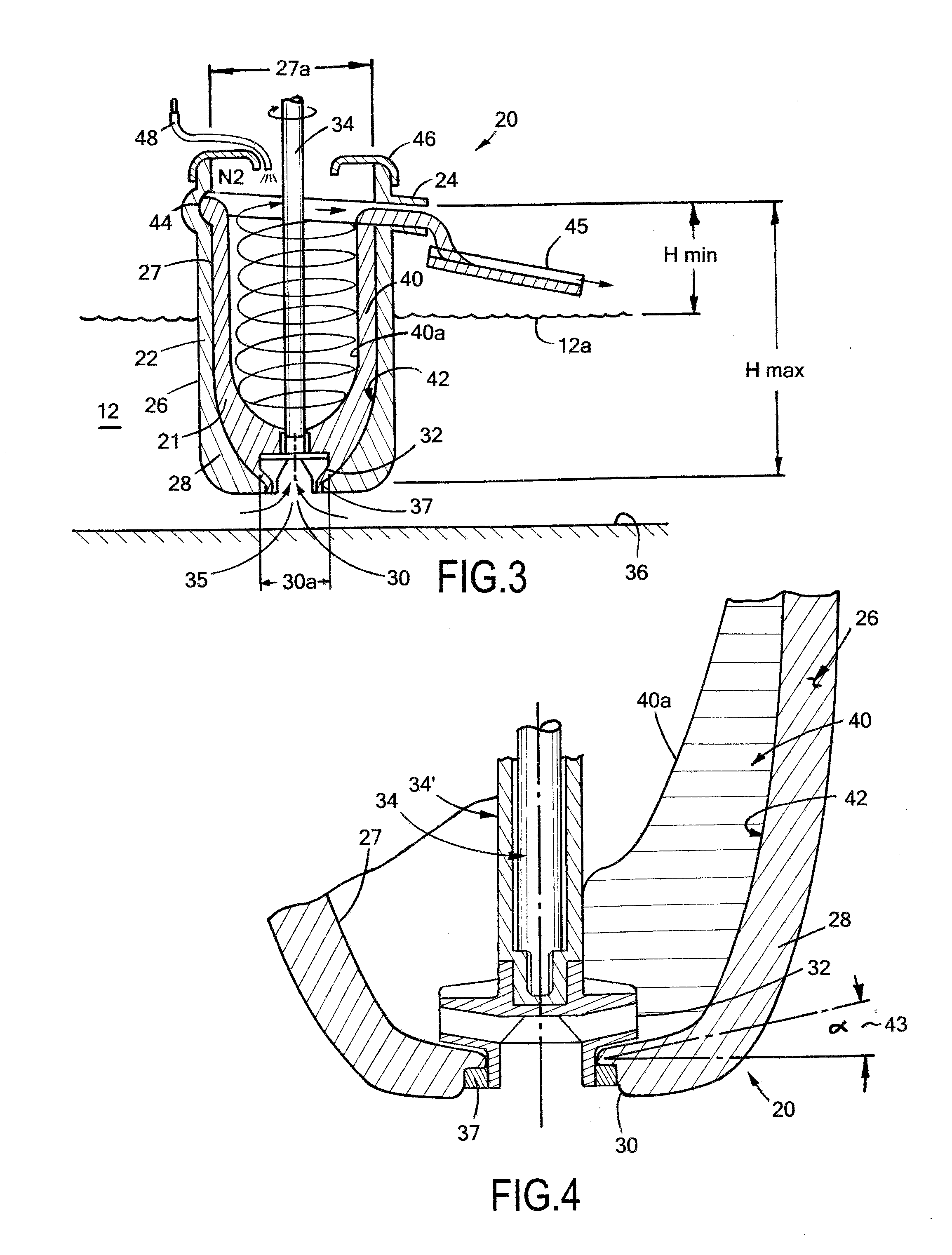
[0044]Referring now to FIG. 3, the present invention is molten metal pump 20 which creates a forced vortex of accelerated molten metal 21 within a vertical tube 22 in the pump to lift or raise the molten metal to an outlet 24 in the upper end of the pump.

[0045]Pump 20 includes an elongated tubular pump body or vessel 26 having a generally vertical inner tube wall 27 and a curved or dome-shaped bottom end 28. As will be discussed in greater detail below, the cavity-defining profile of the bottom end 28 and inner wall are a consequence of the type of vortex selected, ω=Crm, where m is based on a design criteria that depends on the lifting application. For a transfer pump, I have selected m=0. In other embodiments, the profile may be spherical or perhaps elliptical. An inlet opening 30 is formed in the center of the concave lower end 28. A centrifugal impeller 32 is mounted within opening 30 and is rotated by an elongated output shaft 34 which runs concentrically down through the cente...


PUM


Abstract

A pump for processing molten metal having an enlarged tubular body which houses a centrifugal lifting pump at its bottom end. The bottom end has a curved shape that aids in the formation and sustainability of: a) a forced vortex; b) a highly forced vortex; and c) a super forced vortex, depending on the application when it which receives the ejected molten metal from the lifting pump's impeller. The lifting pump is controlled to cause the vortex to climb up the inner wall of the body up to and out of an outlet formed in the upper end of the body. A recirculation centrifugal pump is mounted coaxially to and rotates with the lifting impeller.

Description

CROSS-REFERENCE TO RELATED APPLICATIONS[0001]This application is a continuation-in-part of U.S. patent application Ser. No. 12 / 604,000 filed Oct. 22, 2009 which claims priority of U.S. Utility Patent Application filed Oct. 29, 2008 having Ser. No. 61 / 109,352.FIELD OF THE INVENTION[0002]The present invention relates to lifting, mixing, and recirculating molten metals and, more particularly, to a pump creating a vortex within a lift tube to elevate and mix molten metal.BACKGROUND AND SUMMARY OF THE INVENTION[0003]A typical molten metal facility includes a furnace with a pump for moving molten metal. During the processing of molten metals, such as aluminum and zinc, the molten metal is normally continuously circulated through the furnace by a centrifugal circulation pump to equalize the temperature of the molten bath. These pumps contain a rotating impeller that draws in and accelerates the molten metal creating a laminar-type flow within the furnace.[0004]To transfer the molten metal ...

Claims


Application Information

Patent Timeline
Patent Type & Authority Applications(United States)
IPC IPC(8): F04D29/44
CPCF04D1/14F04D29/445F04D7/065F04D13/021
Inventor MORANDO, JORGE
Owner MORANDO JORGE A
Why Eureka
Try Eureka