Cooling device and an electronic apparatus including the same

a technology of electronic equipment and cooling device, which is applied in the direction of mechanical/solid-state device details, piston pumps, instruments, etc., can solve the problems of large and complicated structure of devices, increased heat generation of cpu, and insufficient conventional air cooling methods solely dependent on heat-sinks. , to achieve the effect of high operating efficiency of motors, simple construction and high cooling efficiency

Inactive Publication Date: 2005-06-02
PANASONIC CORP
View PDF18 Cites 80 Cited by
  • Summary
  • Abstract
  • Description
  • Claims
  • Application Information

AI Technical Summary

Benefits of technology

[0022] The cooling device has a high cooling efficiency as well as a high operating efficiency of the motor while having a simple construction and a small overall size and a small thickness.

Problems solved by technology

As a result, heat generation of the CPU is increased so much that the conventional air cooling method solely dependent upon a heat-sink has become inadequate.
Since the cooling device comprises the combination of these elements, the device has a large and complicated structure which cannot be downsized and also involves cost increase.
In other words, the first conventional cooling device is basically suited for cooling large electronic apparatuses but is not adapted for the current high-performance portable notebook computers featuring a compact, lightweight and slim design and various modes of carriage and use.
That is, the headers are an impediment to a thinner design of the notebook computer.
Unfortunately, the thickness of the reciprocating pump defines a great thickness of the radiator header 114 as a whole, making the notebook computer of slim design impracticable.
Further, the slim notebook computer does not permit the heat absorber header 113 to accommodate the reciprocating pump of the second cooling device.
In addition, vibrations and noises produced by the reciprocating pump adversely affect the semiconductor heat generating device 110 on which the pump would be mounted.
In some cases, the noises may grate on ear.
On these accounts, it is difficult for the second cooling device to contribute the slim design.
The second conventional cooling device encounters a limited cooling capability because the radiator header 114 in contact with the wall of the metal housing 116 has a low heat transferability resulting from a small heat radiating area.
Furthermore, assembly work for the cooling device is complicated.
Thus, the second conventional cooling device has limitations in the reduction of size and thickness of the notebook computers.
The second conventional cooling device with such drawbacks falls short of meeting a demand for further increase of the cooling capability in conjunction with the recent progress of the CPUs.
On the other hand, the conventional pump with the heat exchange function has a large, complicated structure requiring the cooling water passage disposed therein because the coolant is cooled by the independent cooling water.
Hence, the pump is a complicated system difficult to be downsized and also suffers a large number of components and low assembly efficiencies.
Consequently, a good thermal efficiency or cost reduction cannot be expected from this pump.

Method used


Image

  • Cooling device and an electronic apparatus including the same
  • Cooling device and an electronic apparatus including the same
  • Cooling device and an electronic apparatus including the same

Examples


first embodiment

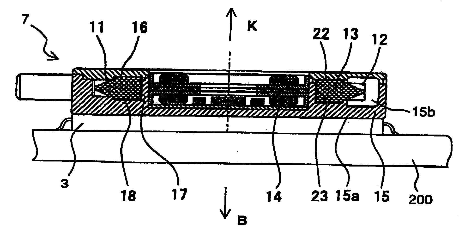
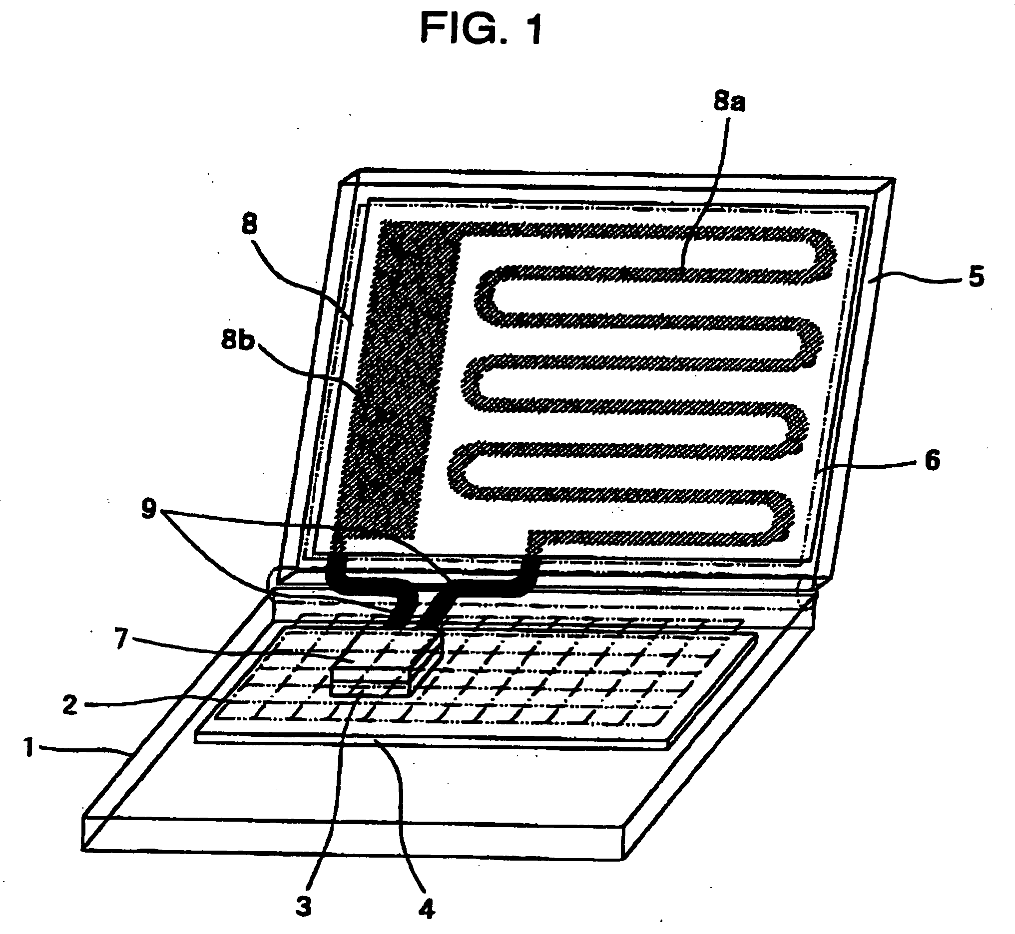
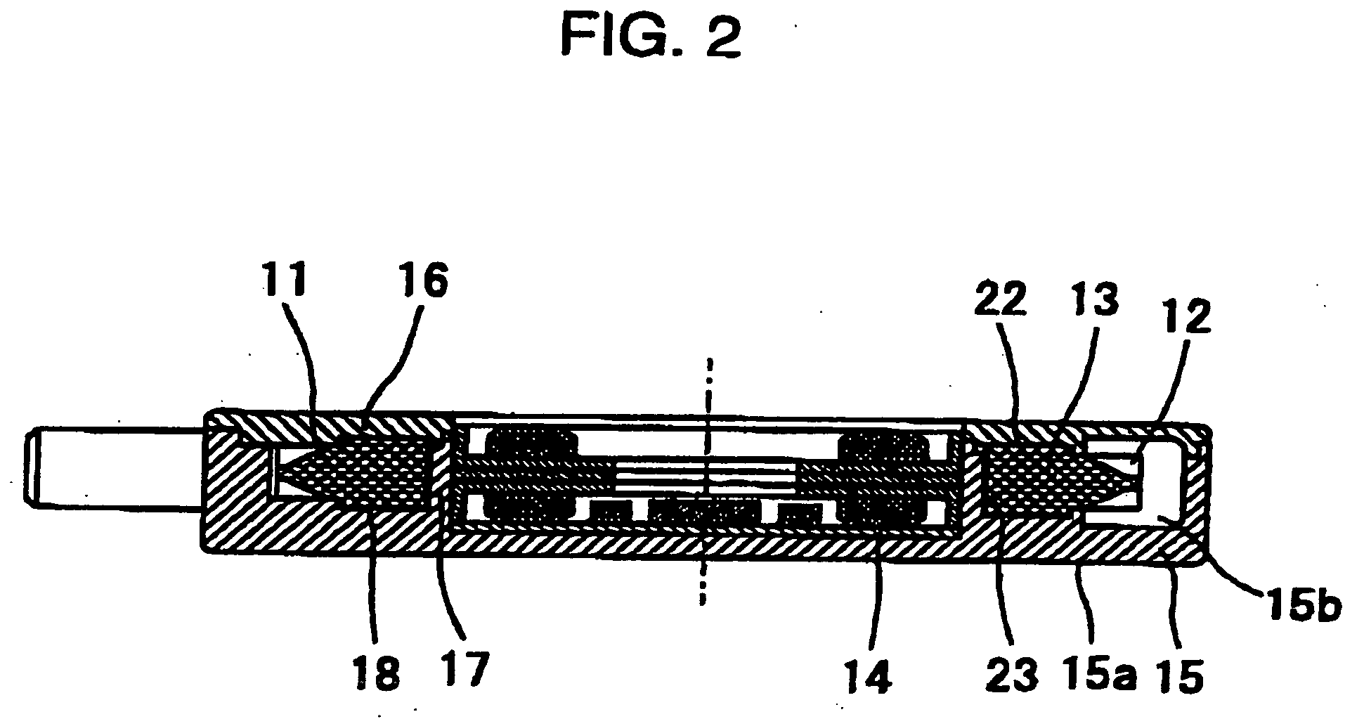
[0083] A cooling device of a first embodiment and an electronic apparatus including the same is designed to interconnect a pump of contact heat exchanger type and a radiator by means of a flexible pipe permitting a second housing to rotate relative to a first housing. The electronic apparatus is a foldable apparatus such as a notebook computer. FIG. 1 is a diagram showing a general construction of the electronic apparatus incorporating the cooling device of the first embodiment, whereas FIG. 2 is a sectional view showing the pump of contact heat exchanger type according to the first embodiment. FIG. 3 is a disassembled perspective view showing the pump of contact heat exchanger type according to the first embodiment whereas FIG. 4 is a sectional view of a principal part showing a flow of a coolant in the pump according to the first embodiment.

[0084] Referring to FIG. 1, a reference numeral 1 represents a first housing such as of a notebook computer; a numeral 2 representing a key b...

second embodiment

[0104] A cooling device according to a second embodiment of the invention and an electronic apparatus including the same is designed to interconnect a pump of contact heat exchanger type and a radiator by means of a pipe and a pivotal member permitting the second housing to rotate relative to the first housing. The electronic apparatus is a foldable apparatus such as a notebook computer. The pump of contact heat exchanger type is constructed the same way as in the first embodiment. FIG. 7 is a diagram showing a general construction of the electronic apparatus incorporating the cooling device according to the second embodiment of the invention. FIG. 8 is a sectional view showing the pivotal member according to the second embodiment of the invention. FIG. 9 is a sectional view showing the pivotal member of the second embodiment of the invention integrated with a removable snap-in type connector.

[0105] Referring to FIG. 7, the reference numeral 1 represents the first housing; the nume...

third embodiment

[0130] The internal configuration of a centrifugal pump 300 of the third exemplary embodiment is now described with reference to FIGS. 38 through 42B. An open-type impeller 301 of the centrifugal pump has a through-hole 301a formed therein and open vanes 302. A magnet rotor 303 is provided along an outer periphery of the impeller 301. A stator 304 is provided inside of the magnet rotor 303. A housing 305 of the pump accommodates the impeller 301, and restores a pressure of kinetic energy given by the impeller 301 to fluid, thus guiding the fluid to an outlet port linked to an outlet passage 310. The housing 305 has a heat-generating electronic component 400 attached thereto, such as an IC, an LSI, or an MPU.

[0131] A pump chamber 305a restores a pressure of kinetic energy given by the vanes 302, thus guiding the fluid to the outlet port. A heat-absorbing surface 305b is provided on a side face of the housing 305 along the pump chamber 305a. The heat-absorbing surface deprives the he...


PUM


Abstract

A cooling device for cooling a heat-generating component includes a circulating passage arranged to have coolant circulate therein, a centrifugal pump including a first case made of metallic material, a second case made of resin material, and an impeller accommodated in the pump chamber, and a radiator provided at the circulating passage and being operable to release heat from the coolant. The first case has a surface arranged to contact the heat-generating component. The second case forms a pump chamber between the first case and the second case. The pump chamber stores the coolant therein. The impeller includes open-type vanes arranged to pressurize the coolant as to have the coolant flow through the circulating passage. The cooling device has a high cooling efficiency as well as a high operating efficiency of the motor while having a simple construction and a small overall size and a small thickness.

Description

RELATED APPLICATIONS [0001] This application is a continuation-in part of the U.S. patent application Ser. No. 10 / 446,152 filed May 28, 2003, which is a continuation-in part of the U.S. patent application Ser. No. 10 / 264,265 filed Oct. 4, 2002, entitled A COOLING DEVICE AND AN ELECTRONIC APPARATUS INCLUDING THE SAME, which relates to and claims priority from Japanese Patent Application No. 2002-139598 filed May 15, 2002, and Japanese Patent Application No. 2003-007168, filed Jan. 15, 2003, the disclosure of both which are hereby incorporated in their entirety by reference.BACKGROUND OF THE INVENTION [0002] 1. Field of the Invention [0003] The present invention relates to a cooling device of an electronic apparatus for cooling a heat-generating electronic component, such as a microprocessor or a CPU, mounted in a case with coolant circulated. [0004] 2. Description of the Related Art [0005] The recent years have seen a dramatic progress in the speed-up of computers while CPUs have muc...

Claims


Application Information

Patent Timeline
Patent Type & Authority Applications(United States)
IPC IPC(8): G06F1/20H01L23/473H05K7/20
CPCG06F1/203G06F2200/201G06F2200/203H01L23/473H01L2924/0002H01L2924/00
Inventor KOGA, SHINYAMATSUDA, TOSHIHIKONIWATSUKINO, KYOSAKAI, TOSHISUKEKUBOTA, TOSHIYUKIHIROSE, MASASHINARAKINO, SHIGERUAIZONO, YOSHIMITSUKASAHARA, KAZUYUKI
Owner PANASONIC CORP
Why Eureka
Try Eureka