Damping unit, damping device and engine test system using damping device

A vibration damping device and test system technology, which is applied in the direction of engine testing, shock absorbers, measuring devices, etc., can solve the problems of different vibration damping requirements of vibration damping devices, poor adaptability of vibration damping measures, damage to turbochargers, etc., to achieve The effect of avoiding supercharger damage, improving adaptability and ensuring stability

Active Publication Date: 2013-02-27
WEICHAI POWER CO LTD
View PDF4 Cites 13 Cited by
  • Summary
  • Abstract
  • Description
  • Claims
  • Application Information

AI Technical Summary

Problems solved by technology

However, for a specific type of engine, the vehicle engine damping block used in this damping measure is usually designed according to the vibration characteristics of the specific type of engine, and can only effectively reduce the vibration generated during the operation of the specific type of engine. However, different engines The vibration characteristics are also different, and the vibration damping requirements for the damping device are also different. The vehicle damping block for a specific engine is not suitable for other different types of engines
[0004] Therefore, the vibration reduction measures of the existing engine bench tests are poor in adaptability, and cannot effectively guarantee the stability of engine test runs for all models
In addition, the four installation points of this scheme use the same vibration damping block. When the vibration of the engine flywheel shell end is greater than that of other installation points, it is very easy to cause the supercharger screw to break, and then damage the supercharger.

Method used


Image

  • Damping unit, damping device and engine test system using damping device
  • Damping unit, damping device and engine test system using damping device
  • Damping unit, damping device and engine test system using damping device

Examples


Embodiment Construction

[0029] The core of the invention is to provide a vibration damping unit, which is used for vibration damping in the test and detection process of different types of engines, and has better adaptability. The present embodiment will be described in detail below in conjunction with the accompanying drawings.

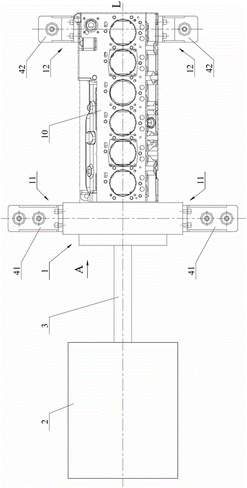
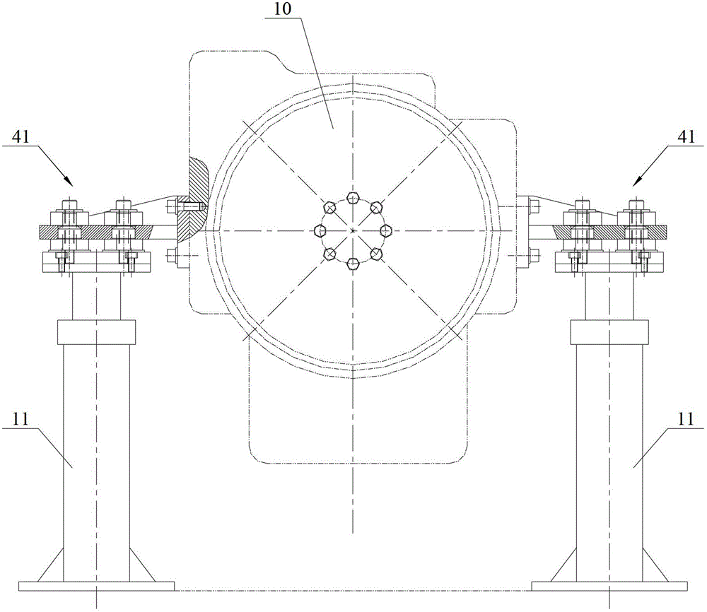
[0030] See figure 1 and figure 2 ,in, figure 1 It is a top view of the engine test system described in this embodiment; figure 2 for figure 1 A view of A, the figure does not show the dynamometer.

[0031] Same as the prior art, the engine test system includes a bench device 1 for carrying the engine to be tested 10, a dynamometer 2 and a transmission shaft 3 connecting the dynamometer 2 and the crankshaft of the engine to be tested 10; The dynamometer 2 measures the running data of the engine 10 .

[0032] combine figure 1 and figure 2 As shown, two sets of supporting devices are arranged on the platform device 1, and the two supporting devices of each group are...


PUM


Abstract

The invention discloses a damping unit, which comprises a first elastic element, a second elastic element and a guide sleeve, wherein the second elastic element is arranged under the first elastic element and is abutted against the first elastic element, the guide sleeve is inserted in inner holes of the first elastic element and the second elastic element, the length of the guide sleeve is smaller than the sum of the lengths of the inner holes of the first elastic element and the second elastic element in the axial direction of the guide sleeve, and an accommodating part is arranged between the first elastic element and the second elastic element and is used for clamping and accommodating an element to be damped. The damping unit has the advantages that reliable relative position relationship of the two elastic elements can be maintained in the pressing and resetting process; on the basis of ensuring the operation stability of the damping unit under the bearing state, the damping unit is suitable for the connecting brackets of engines different in models, so the adaptability is greatly improved. On the basis of the damping unit, the invention also provides a damping device using the damping unit and an engine test system using the damping device.

Description

technical field [0001] The invention relates to engine bench test technology, in particular to a vibration damping unit, a vibration damping device and an engine test system using the vibration damping device. Background technique [0002] Before leaving the factory, most engines need to be tested on a bench, and the test results can only be put into use after meeting the design requirements. At present, in the process of engine test and test, the operating data of the engine is measured by a dynamometer, and the dynamometer and the engine are connected by a drive shaft. Based on its working principle and structural characteristics, the engine will generate a large Obviously, only by eliminating this vibration or controlling it within a certain range can the data measured by the dynamometer be true and accurate. [0003] In the prior art, in order to reduce the vibration generated during the engine bench test, vibration damping measures are usually adopted. The engine vehic...

Claims


Application Information

Patent Timeline
Patent Type & Authority Applications(China)
IPC IPC(8): F16F3/00F16F3/087F16F7/00G01M15/02
Inventor 占翠玲吴欣容赵海存秦振振
Owner WEICHAI POWER CO LTD
Why Eureka
Try Eureka