Lamp and lifting device for same

A lifting device and guide cylinder technology, applied in lighting devices, lighting auxiliary devices, fixed lighting devices, etc., can solve the problems of high cost and complex structure, and achieve the effect of convenient installation

Inactive Publication Date: 2014-12-03
SHENZHEN OCEANS KING LIGHTING ENG CO LTD +1
View PDF7 Cites 0 Cited by
  • Summary
  • Abstract
  • Description
  • Claims
  • Application Information

AI Technical Summary

Problems solved by technology

Some suspended lamps use an auxiliary remote control device to adjust the height of the suspended lamps, but this method is complex in structure and high in cost

Method used


Image

  • Lamp and lifting device for same
  • Lamp and lifting device for same

Examples


Embodiment Construction

[0016] In order to further illustrate the principle and structure of the present invention, the preferred embodiments of the present invention will now be described in detail with reference to the accompanying drawings.

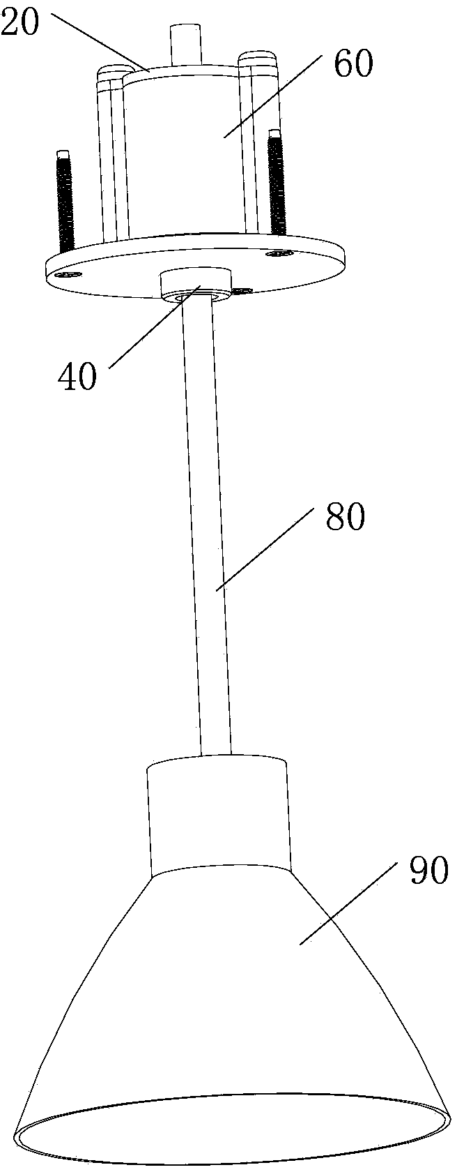
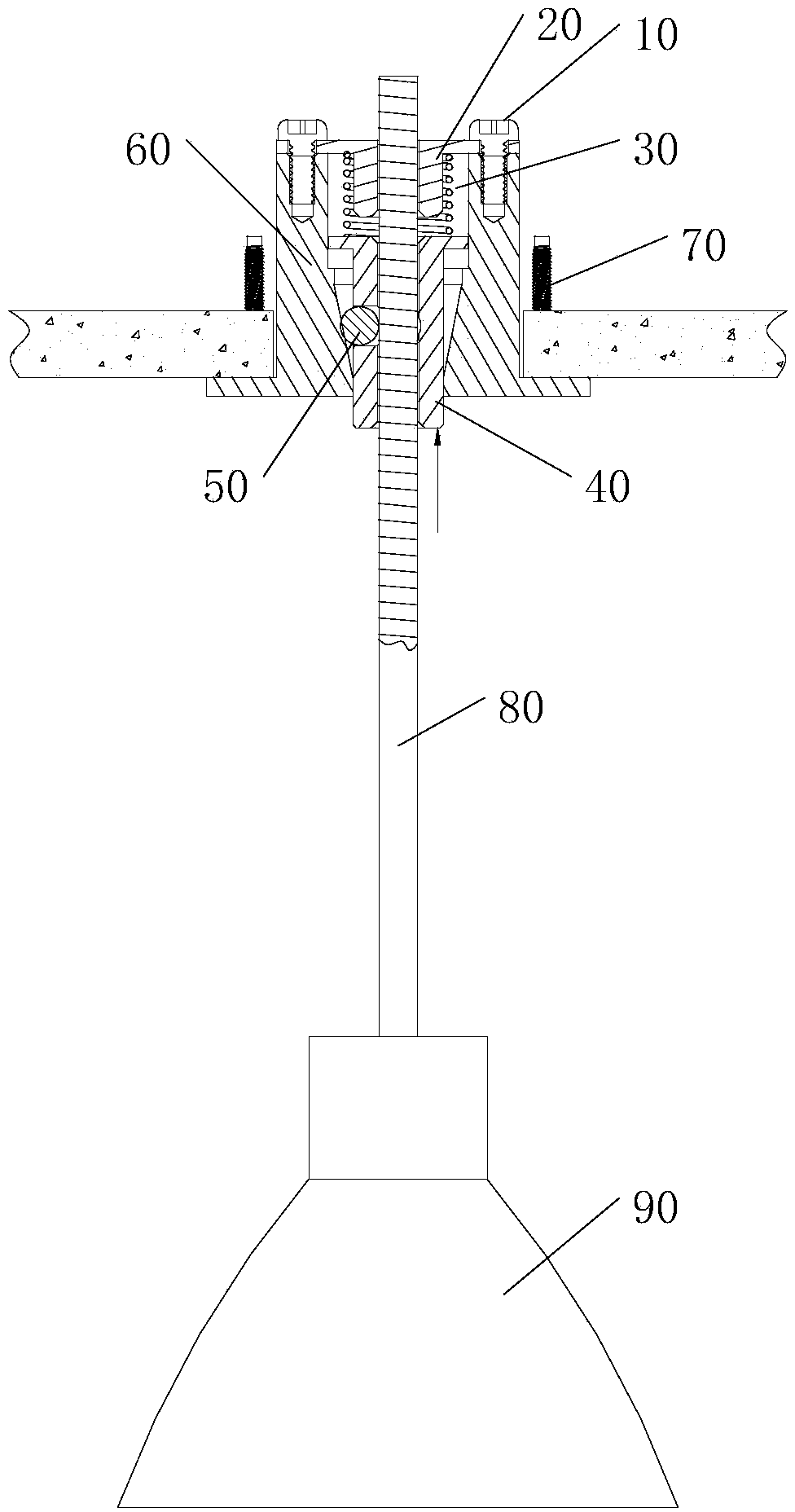
[0017] figure 1 It shows a perspective view of the lamp provided by the present invention. The lamp includes a lifting device and a lamp holder 90. The lifting device includes a sleeve 60 and a plurality of balls (see figure 2 Reference numeral 50), guide cylinder 40, spring (see figure 2 Reference numeral 30), end cap 20, and boom 80.

[0018] The sleeve 60 is provided with a first open end and a second open end. Wherein, the first open end is smaller than the second open end. The first open end allows the guide tube 40 to pass through. The second open end is connected and fixed with the end cover 20.

[0019] The lamp cap 90 is fixed to the different end of the boom 80 and the guide tube 40 to connect with the lifting device. Preferably, one end of the lam...


PUM


Abstract

The invention provides a lamp and a lifting device for the same. The lifting device is characterized by comprising a sleeve, a plurality of balls, a guide tube, a spring, an end cover and a hanger rod, wherein the guide tube is pressed towards a second port to move towards the second port, the balls move towards the inner sidewall of the sleeve to be scattered, and the hanger rod can move in an extension direction of the guide tube; when the guide tube is not pressed towards the second port, the guide tube is driven by the spring to move towards a first port, the balls move away from inner sidewall of the sleeve to be gathered under the extrusion of the inner sidewall of the sleeve, and the hanger rod is fixed by the gathering and extrusion of the balls.

Description

technical field [0001] The invention relates to the field of lamp design. Background technique [0002] The heights of commonly used hanging lamps are mostly non-adjustable, and the products have a fixed hanging height after manufacture. Some suspended lamps use an auxiliary remote control device to adjust the height of the suspended lamp, but this method has a complicated structure and high cost. Contents of the invention [0003] The invention provides a lifting device, which is characterized in that it comprises: a sleeve, the inner wall of the sleeve is conical and provided with a first open end and a second open end, wherein the first open end is smaller than the The second opening end; a plurality of balls; a guide cylinder, the extension direction of the guide cylinder is provided with a first through hole, and the outer wall of the guide cylinder is provided with a plurality of through holes for the balls to be placed, each The through hole is adapted to one of t...

Claims


Application Information

Patent Timeline
IPC IPC(8): F21S8/06F21V21/22
Inventor 周明杰蔡华
Owner SHENZHEN OCEANS KING LIGHTING ENG CO LTD
Why Eureka
Try Eureka