Soot blowing method and device for horizontal flue of π-shaped boiler

A boiler horizontal flue and soot blowing device technology, applied in the direction of combustion method, combustion product treatment, solid residue removal, etc., can solve flue gas temperature fluctuation due to temperature difference, cannot accurately reflect flue ash accumulation, and achieve No problems such as soot blowing requirements can be achieved, and the effect of reducing renovation cost, good disturbance effect, shortening construction period and construction difficulty can be achieved

Active Publication Date: 2016-08-24
HUADIAN ELECTRIC POWER SCI INST CO LTD
View PDF7 Cites 3 Cited by
  • Summary
  • Abstract
  • Description
  • Claims
  • Application Information

AI Technical Summary

Problems solved by technology

The above-mentioned soot blowing method solves the problem that the existing soot blowing system cannot perform soot blowing according to the actual soot accumulation on the surface of the heat exchange tubes, but the following problems still exist: 1. Since its normal operating temperature is preset, it does not According to the flue gas temperature change in the flue gas, the temperature difference obtained by this method will fluctuate greatly due to the flue gas temperature: when the flue gas temperature is high, even if there is no ash or less ash in the flue, The temperature difference will still meet the soot blowing requirements, resulting in "over blowing"; when the flue gas temperature is low, even if there is a lot of dust in the flue, the temperature difference still cannot meet the soot blowing requirements, resulting in "under blowing"; 2 .When the soot blowing is in progress or after the soot blowing is completed, due to the non-instantaneous temperature change, there is a delay in the temperature detection, which will cause the controller to still send the soot blowing signal to the soot blowing system during the soot blowing process or after the soot blowing is completed, resulting in "over blowing", and the soot blowing gas used in the soot blowing process will affect the temperature in the flue. If the temperature of the soot blowing gas is too high, the controller may continue to send the soot blowing signal to the soot blowing system, resulting in the continuous "overshooting" of the system's dead cycle. 3. The detected temperature is not the internal temperature of the flue but the outlet flue gas temperature. This temperature will be affected by the length of the flue or the ambient temperature, and cannot accurately reflect the ash accumulation in the flue.

Method used


Image

  • Soot blowing method and device for horizontal flue of π-shaped boiler
  • Soot blowing method and device for horizontal flue of π-shaped boiler

Examples


Embodiment 1

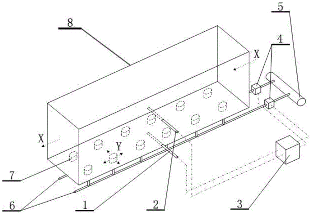
[0036] Such as figure 1 Shown, the soot blowing method of the present embodiment is made up of following steps:

[0037] Step A, measure the instant temperature T1 at this point of the flue 8 by setting the first temperature detector 1 on the bottom wall of the flue 8 at the horizontal direction of the flue 8, that is, at 1 / 3 of the smoke flow direction X in the figure; The second temperature detector 2 arranged at 2 / 3 of the horizontal direction of the flue 8 and 1 / 4 of the height of the flue 8 measures the instant temperature T2 of this point of the flue 8;

[0038] Step B, input T1 and T2 into the PID (proportional-integral-derivative) control module 3 to obtain the difference ΔT between T2 and T1;

[0039] Step C, when ΔT is greater than or equal to 5°C, the PID control module 3 sends a soot blowing signal to the soot blowing system. Pass compressed air into the flue 8 for 10 seconds, and return to step A after the soot blowing is completed; when ΔT is less than 5°C, ret...

Embodiment 2

[0043] Such as figure 1 Shown, the soot blowing method of the present embodiment is made up of following steps:

[0044] Step A, measure the instant temperature T1 at this point of the flue 8 by setting the first temperature detector 1 at the midpoint of the flue 8 in the horizontal direction of the flue 8, that is, the middle point of the smoke flow direction X in the figure, and at 1 / 8 of the height of the flue 8; Measure the instant temperature T2 at this point of the flue 8 by setting it at the middle point in the horizontal direction of the flue 8, in the same section as the first temperature detector 1, and at the second temperature detector 2 at 1 / 2 of the height of the flue 8;

[0045] Step B, input T1 and T2 into the PID (proportional-integral-derivative) control module 3 to obtain the difference ΔT between T2 and T1;

[0046] Step C, when ΔT is greater than or equal to 5°C, the PID control module 3 sends a soot blowing signal to the soot blowing system and no longer...

Embodiment 3

[0050] Such as figure 1 Shown, the soot blowing method of the present embodiment is made up of following steps:

[0051] Step A, measure the instant temperature T1 at this point of the flue 8 by setting the first temperature detector 1 on the horizontal direction of the flue 8, that is, the middle point of the smoke flow direction X direction in the figure, and the bottom wall of the flue 8; The middle point in the horizontal direction of the flue 8 is the same section as the first temperature detector 1, and the second temperature detector 2 at 1 / 2 of the height of the flue 8 measures the instant temperature T2 at this point of the flue 8;

[0052] Step B, input T1 and T2 into the PID (proportional-integral-derivative) control module 3 to obtain the difference ΔT between T2 and T1;

[0053] Step C, when ΔT is greater than or equal to 2°C, the PID control module 3 sends a soot blowing signal to the soot blowing system and no longer sends the soot blowing signal to the soot bl...


PUM


Abstract

The invention relates to a soot blowing method and device for a horizontal flue of a π-shaped boiler, which consists of a temperature measurement system, a control module and a soot blowing system. The temperature measurement system includes a first temperature detection device arranged on the flue wall device and a second temperature detector, the soot blowing system includes an air supply pipe, a solenoid valve arranged on the air supply pipe, and a wind cap connected with the air supply pipe and arranged on the bottom wall of the flue, and the wind cap is evenly distributed; the The first temperature detector and the second temperature detector are connected to a control module, and the control module is connected to an electromagnetic valve. It is a soot blowing method and device for a horizontal flue of a π-shaped boiler that can automatically complete the dust removal work, effectively reduce "overblowing" or "underblowing", and accurately monitor the flue dust accumulation.

Description

technical field [0001] The invention relates to a soot blowing method and device, in particular to a soot blowing method and device for a horizontal flue of a π-shaped boiler. Background technique [0002] At present, there is a common problem in π-shaped boilers, that is, the serious ash accumulation problem in the horizontal flue of π-shaped boilers. The main reason is that the flue gas contains smoke and dust, and the wind speed at the bottom of the horizontal flue is low, which is easy to deposit dust. With the increase of ash accumulation, the flow area of ​​the horizontal flue of the π-shaped boiler will change, affecting the flow of the flue. field distribution, so that the boiler cannot operate in the design state, which will lead to poor heat transfer effect of the superheater or reheater, and the heat transfer effect of the heat transfer tubes and water-cooled walls buried in the smoke and dust will be reduced, and the water-cooled walls and other heat transfer tub...

Claims


Application Information

Patent Timeline
Patent Type & Authority Patents(China)
IPC IPC(8): F23J3/02
Inventor 陈剑吴桂福薛志鹏廖永浩郝建刚何建乐马龙信
Owner HUADIAN ELECTRIC POWER SCI INST CO LTD
Why Eureka
Try Eureka