Soot blowing method and device for W flame boiler air chamber

An air chamber and boiler technology, applied in boiler cleaning control device, combustion method, combustion product treatment, etc., can solve the problems of temperature difference flue gas temperature fluctuation, failure to meet soot blowing requirements, soot blowing, etc.

Active Publication Date: 2017-01-11
HUADIAN ELECTRIC POWER SCI INST CO LTD
View PDF9 Cites 0 Cited by
  • Summary
  • Abstract
  • Description
  • Claims
  • Application Information

AI Technical Summary

Problems solved by technology

The above-mentioned soot blowing method solves the problem that the existing soot blowing system cannot perform soot blowing according to the actual soot accumulation on the surface of the heat exchange tubes, but the following problems still exist: 1. Since its normal operating temperature is preset, it does not According to the flue gas temperature change in the air chamber, the temperature difference obtained by this method will fluctuate greatly due to the flue gas temperature: when the flue gas temperature is high, even if there is no dust accumulation or less dust accumulation in the air chamber, The temperature difference will still meet the soot blowing requirements, resulting in "over blowing"; when the flue gas temperature is low, even if there is a lot of dust in the air chamber, the temperature difference still cannot meet the soot blowing requirements, resulting in "under blowing"; 2 .When the soot blowing is in progress or after the soot blowing is completed, due to the non-instantaneous temperature change, there is a delay in the temperature detection, which will cause the controller to still send the soot blowing signal to the soot blowing system during the soot blowing process or after the soot blowing is completed, resulting in "over Blowing”, and the soot blowing gas used in the soot blowing process will affect the temperature in the air chamber. If the temperature of the soot blowing gas is too high, the controller may continue to send soot blowing signals to the soot blowing system, resulting in the continuous “over 3. The detected temperature is not the internal temperature of the air chamber but the outlet flue gas temperature. This temperature will be affected by the length of the air chamber or the ambient temperature, and cannot accurately reflect the dust accumulation in the air chamber.

Method used


Image

  • Soot blowing method and device for W flame boiler air chamber
  • Soot blowing method and device for W flame boiler air chamber
  • Soot blowing method and device for W flame boiler air chamber

Examples


Embodiment 1

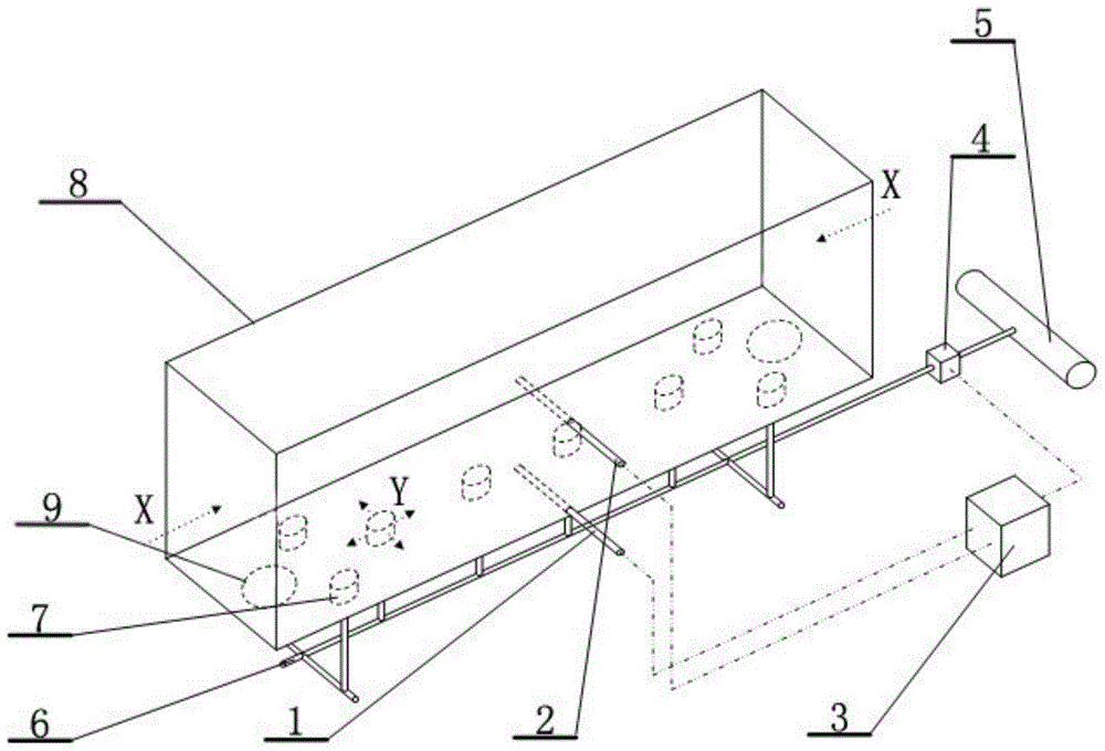
[0037] Such as figure 1 Shown, the soot blowing method of the present embodiment is made up of following steps:

[0038] Step A, by setting the first temperature detector 1 on the bottom wall of the air chamber 8 at the horizontal direction of the air chamber 8, that is, at 1 / 3 of the X direction of the smoke flow in the figure, to measure the instant temperature T1 of the point of the air chamber 8; The second temperature detector 2 arranged at 2 / 3 of the horizontal direction of the air chamber 8 and 1 / 4 of the height of the air chamber 8 measures the instant temperature T2 at this point of the air chamber 8;

[0039] Step B, input T1 and T2 into the PID (proportional-integral-derivative) control module 3 to obtain the difference ΔT between T2 and T1;

[0040] Step C, when ΔT is greater than or equal to 5°C, the PID control module 3 sends a soot blowing signal to the soot blowing system. Air chamber 8 is fed with compressed air for 1000 seconds. After the soot blowing work ...

Embodiment 2

[0044] Such as figure 1 Shown, the soot blowing method of the present embodiment is made up of following steps:

[0045] Step A, measure the instant temperature T1 at this point of the air chamber 8 by setting the first temperature detector 1 on the bottom wall of the air chamber 8 in the horizontal direction of the air chamber 8, that is, the middle point of the smoke flow direction X direction in the figure; The middle point in the horizontal direction of the air chamber 8 is the same section as the first temperature detector 1, and the second temperature detector 2 at the height 1 / 2 of the air chamber 8 measures the instant temperature T2 at this point of the air chamber 8;

[0046] Step B, input T1 and T2 into the PID (proportional-integral-derivative) control module 3 to obtain the difference ΔT between T2 and T1;

[0047] Step C, when ΔT is greater than or equal to 2°C, the PID control module 3 sends a soot blowing signal to the soot blowing system. 60 seconds of hot p...


PUM


Abstract

The invention relates to a soot blowing method and device for a W-flame boiler wind chamber. The device is composed of a temperature measurement system, a control module and a soot blowing system. The temperature measurement system comprises a first temperature detector and a second temperature detector which are arranged on the wall of the wind chamber. The soot blowing system comprises an air supply pipe, a solenoid valve on the air supply pipe and air caps which are connected with the air supply pipe and arranged on the bottom wall of the air chamber. The first temperature detector and the second temperature detector are connected with the control module, and the control module is connected with the solenoid valve. According to the soot blowing method and device for the W-flame boiler wind chamber, soot removing work can be completed automatically, over-blowing or under-blowing can be effectively reduced, and the soot formation condition of the wind chamber is monitored precisely.

Description

technical field [0001] The invention relates to a soot blowing method and device, in particular to a soot blowing method and device for a wind chamber of a W flame boiler. Background technique [0002] At present, there is a common problem in W-flame boilers, that is, the problem of dust accumulation in the air chamber of W-flame boilers is serious. The anti-slagging wind is provided by the pipeline leading out from the bottom of the air chamber, while the hot flue gas and the cold secondary air carry out the cold and heat exchange process in the air preheater, entraining the smoke and dust in the flue gas to the W flame boiler air chamber , resulting in soot accumulation at the bottom of the air chamber of the W flame boiler, which can easily block the anti-slagging air inlet, resulting in a decrease in the anti-slagging air volume, which cannot meet the design requirements, causing slagging at the bottom of the lower furnace, and affecting the heat transfer of the boiler w...

Claims


Application Information

Patent Timeline
Patent Type & Authority Patents(China)
IPC IPC(8): F22B37/56F23J3/00
Inventor 薛志鹏吴桂福陈剑廖永浩郝建刚葛伟陈军华汪正海
Owner HUADIAN ELECTRIC POWER SCI INST CO LTD
Why Eureka
Try Eureka