Steel pipe water pressure automatic testing machine

A technology for testing machines and steel pipes, applied in measuring devices, using stable tension/pressure to test material strength, using liquid/vacuum to measure liquid tightness, etc., can solve the problem of increasing the work intensity of online testing personnel Safety and other issues

Active Publication Date: 2016-05-18
CHANGSHUSMLESS STEEL TUBE
View PDF7 Cites 0 Cited by
  • Summary
  • Abstract
  • Description
  • Claims
  • Application Information

AI Technical Summary

Problems solved by technology

However, since the traction mechanism usually does not have the function of lifting or lowering the steel pipe, if there is a lack of extraction of the steel pipe drawn by the steel pipe traction mechanism and lifting upwards, the steel pipe can be properly matched to the height of the steel pipe clamping mechanism for steel pipe clamping. If the steel pipe lifting mechanism clamped by the holding mechanism can only be done by hand, the manual work will not only lose safety, but also increase the work intensity of the online inspection personnel.

Method used


Image

  • Steel pipe water pressure automatic testing machine
  • Steel pipe water pressure automatic testing machine
  • Steel pipe water pressure automatic testing machine

Examples


Embodiment Construction

[0026] In order to enable the examiners of the patent office, especially the public, to understand the technical essence and beneficial effects of the present invention more clearly, the applicant will describe in detail the following in the form of examples, but none of the descriptions to the examples is an explanation of the solutions of the present invention. Any equivalent transformation made according to the concept of the present invention which is merely formal but not substantive shall be regarded as the scope of the technical solution of the present invention.

[0027] In the following descriptions, all concepts involving up, down, left, right, front and rear directionality (or orientation) are for the position state of the picture being described, and the purpose is to facilitate the public Therefore, it cannot be understood as a special limitation on the technical solution provided by the present invention.

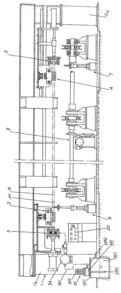
[0028] See figure 1 , provided: a frame 1; a steel pipe...


PUM


Abstract

The invention relates to an automatic detector for water pressure of a steel pipe, belonging to the technical field of a steel pipe water pressure testing machine. The automatic detector for the water pressure of the steel pipe comprises a stander, a steel pipe left clamping mechanism, a steel pipe water injecting mechanism, a steel pipe right clamping mechanism, a steel pipe end opening sealing mechanism, a steel pipe left lifting mechanism and a steel pipe right lifting mechanism, wherein the steel pipe left clamping mechanism and the steel pipe water injecting mechanism are arranged on the left end of the stander; the steel pipe right clamping mechanism and the steel pipe end opening sealing mechanism are arranged on the right end of the stander; the part, which corresponds to the right side of the steel pipe left clamping mechanism, of the steel pipe left lifting mechanism is supported on a terrace, and the part, which corresponds to the right side of the steel pipe right clamping mechanism, of the steel pipe right lifting mechanism is supported on the terrace; the steel pipe left lifting mechanism comprises a left lifting acting cylinder fixed seat, a left lifting acting cylinder, a pair of left carrier pipe frame guide rods and a left carrier pipe frame. By adopting the automatic detector, the overstocking phenomenon of the to-be-detected steel pipe can be avoided; the operating intensity is alleviated, and the safety is guaranteed; the phenomenon that the unqualified flawed steel pipe is mixed with the qualified steel pipe can be prevented; the steel pipe is raised upwards by the steel pipe left lifting mechanism and the steel pipe right lifting mechanism to the height in which the left clamping mechanism and the right clamping mechanism are arranged, and the steel pipe left lifting mechanism and the steel pipe right lifting mechanism are also used for receiving the detected steel pipe and returning the detected steel pipe to a steel pipe drawing mechanism to be unloaded by the steel pipe drawing mechanism.

Description

technical field [0001] The invention belongs to the technical field of steel pipe hydraulic testing machinery, and in particular relates to an automatic steel pipe hydraulic testing machine. Background technique [0002] The steel pipes mentioned above mainly refer to seamless steel pipes (hereinafter the same), and seamless steel pipes include hot-rolled seamless steel pipes and cold-rolled and cold-drawn seamless steel pipes. Because the seamless steel pipe has a hollow cross-section, it is widely used as a pipe for transporting fluids, such as transporting oil, natural gas, gas, water, and so on. Seamless steel pipes are widely used in the field of military industry, industry and even construction. As far as the field of military industry is concerned, it is used for satellites, aircraft, ships, etc. Power generation facilities, as far as the construction field is concerned, are mostly used as scaffolding. [0003] In order to ensure the quality of the steel pipe, in ad...

Claims


Application Information

Patent Timeline
Patent Type & Authority Patents(China)
IPC IPC(8): G01N3/12G01N3/02G01M3/02
Inventor 叶青周云峰赵剑华吴益周国强张小龙唐喜国钱俊郭建华陆雪琴
Owner CHANGSHUSMLESS STEEL TUBE
Why Eureka
Try Eureka