
Field wiring connector

A technology for on-site production of wires and connectors, applied in the direction of clamping/spring connections, devices to prevent wrong connections, etc., can solve the problems of increasing the difficulty of screw processing, inapplicability, and increasing the production cost of crimping screws, etc.

Active Publication Date: 2014-12-03
CHINA AVIATION OPTICAL-ELECTRICAL TECH CO LTD
View PDF5 Cites 5 Cited by
  • Summary
  • Abstract
  • Description
  • Claims
  • Application Information

AI Technical Summary

Problems solved by technology

In actual use, in order to prevent the crimping screw from coming out of the screw hole, it is often necessary to set up a corresponding anti-loosening structure to limit and prevent the crimping screw from coming off. The existing anti-loosening structure is to set a corresponding closing port on the metal shell structure, this method has great limitations, because the screw needs to be attached to the metal shell to achieve anti-off, which leads to the fact that the screw must be in contact with the metal shell, which makes the existing anti-off The structure has great limitations, and it cannot be used in the working environment that requires no contact between the crimping screw and the metal shell; in addition, it is also necessary to process a matching structure on the crimping screw to cooperate with the closing structure , which increases the difficulty of screw processing and increases the production cost of crimping screws

Method used


Image

  • Field wiring connector
  • Field wiring connector
  • Field wiring connector

Examples


Embodiment Construction

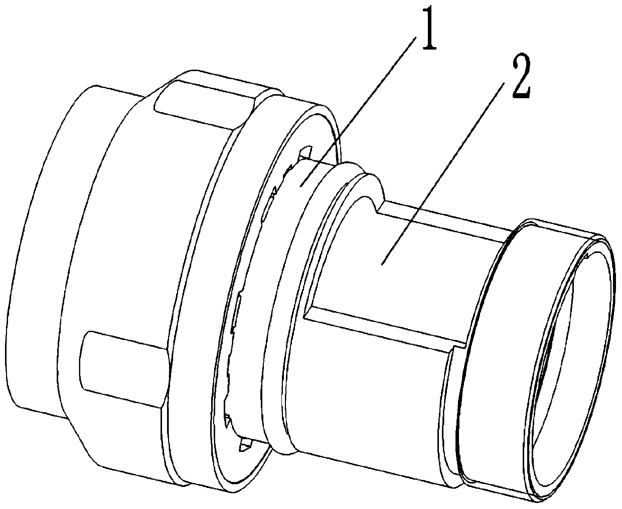
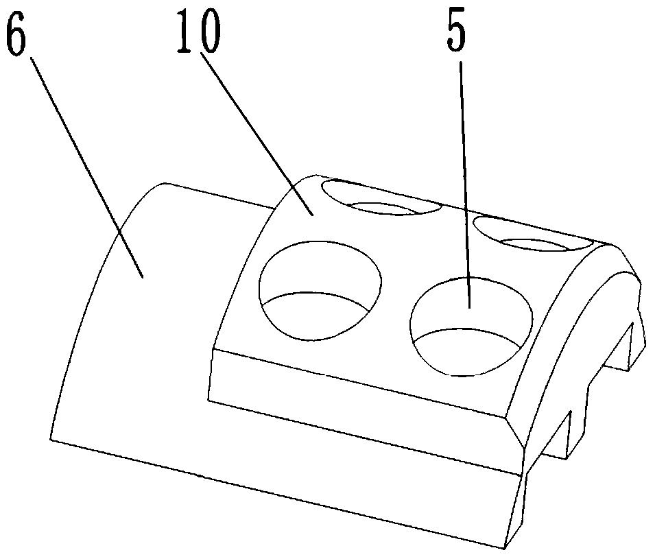
[0019] Examples of on-site wiring connectors Figure 1-7 As shown: it includes a metal shell 1 with a plug-in end at the front end. An axial mounting hole extending axially along the front and rear directions is arranged in the metal shell. An insulator 8 with a built-in contact 4 is installed in the axial mounting hole. On the contact A wire core perforation 9 for the corresponding cable core is provided, and a screw perforation 12 is arranged on the hole wall of the wire core perforation, and the screw perforation is equipped with a press for fixing the cable core to the corresponding wire core perforation. wire screw 3. The insulator is provided with a platform 11 connected to the outer peripheral surface of the insulator through a concave step, and an insulator perforation 13 corresponding to the screw perforation is provided on the platform, and a radial installation gap is formed between the table top of the platform and the wall of the axial installation hole , the rad...


PUM


Abstract

The invention relates to a field wiring connector comprising a metallic housing. The front end of the metallic housing is a plugging end. An insulator with a built-in contact member is installed in the axial installing holes of the metallic housing. Wire pressing screws pass through screw holes on the contact member. A radial installing gap is arranged between the insulator and the wall of the axial installing holes. An insulating anti-separation member is fixedly disposed in the radial installing gap through a fixing structure. Moving chambers are arranged between the insulating anti-separation member and the insulator and the wire pressing screws may perform reciprocating motion in the moving chambers along the axis direction of corresponding screw holes. The insulating anti-separation member is provided with screwdriver holes corresponding to the positions of the screw holes and a corresponding screwdriver may pass through the screwdriver holes and then applies torque to the wire pressing screws. The insulating anti-separation member is also provided with a screw anti-separation structure used for being in blocking cooperation with the wire pressing screws so as to define a limitation within which the wire pressing screws may move towards the direction far away from the screw holes. The field wiring connector may prevent the wire pressing screws from being separated and guarantee non-conduction between the wire pressing screws and the metallic housing.

Description

technical field [0001] The invention relates to a field-made wire connector for transmitting electrical signals. Background technique [0002] The existing field-made wire connectors include a housing, an insulator with a built-in contact is installed in the axial mounting hole of the housing, and the contact is provided with a core perforation for the corresponding cable core to wear, and a hole for the core perforation Screw holes are arranged on the wall, and crimping screws for fixing the cable cores in the corresponding wire core holes are installed in the screw holes. In actual use, in order to prevent the crimping screw from coming out of the screw hole, it is often necessary to set up a corresponding anti-loosening structure to limit and prevent the crimping screw from coming off. The existing anti-loosening structure is to set a corresponding closing port on the metal shell structure, this method has great limitations, because the screw needs to be attached to the ...

Claims


Application Information

Patent Timeline
Patent Type & Authority Applications(China)
IPC IPC(8): H01R13/641H01R4/28
Inventor 冯冲吴泽华
Owner CHINA AVIATION OPTICAL-ELECTRICAL TECH CO LTD
Learn More