

Linear and planar motor coil winding device and method
A flat motor and coil technology, applied in electromechanical devices, manufacturing motor generators, electrical components, etc., can solve the problems of single-shaped coils of winding molds, insufficient connection between turns and turns, and difficulty in ensuring dimensional accuracy. Winding for accurate and effective results
- Summary
- Abstract
- Description
- Claims
- Application Information
AI Technical Summary
Problems solved by technology
Method used
Image

Examples
Embodiment 1
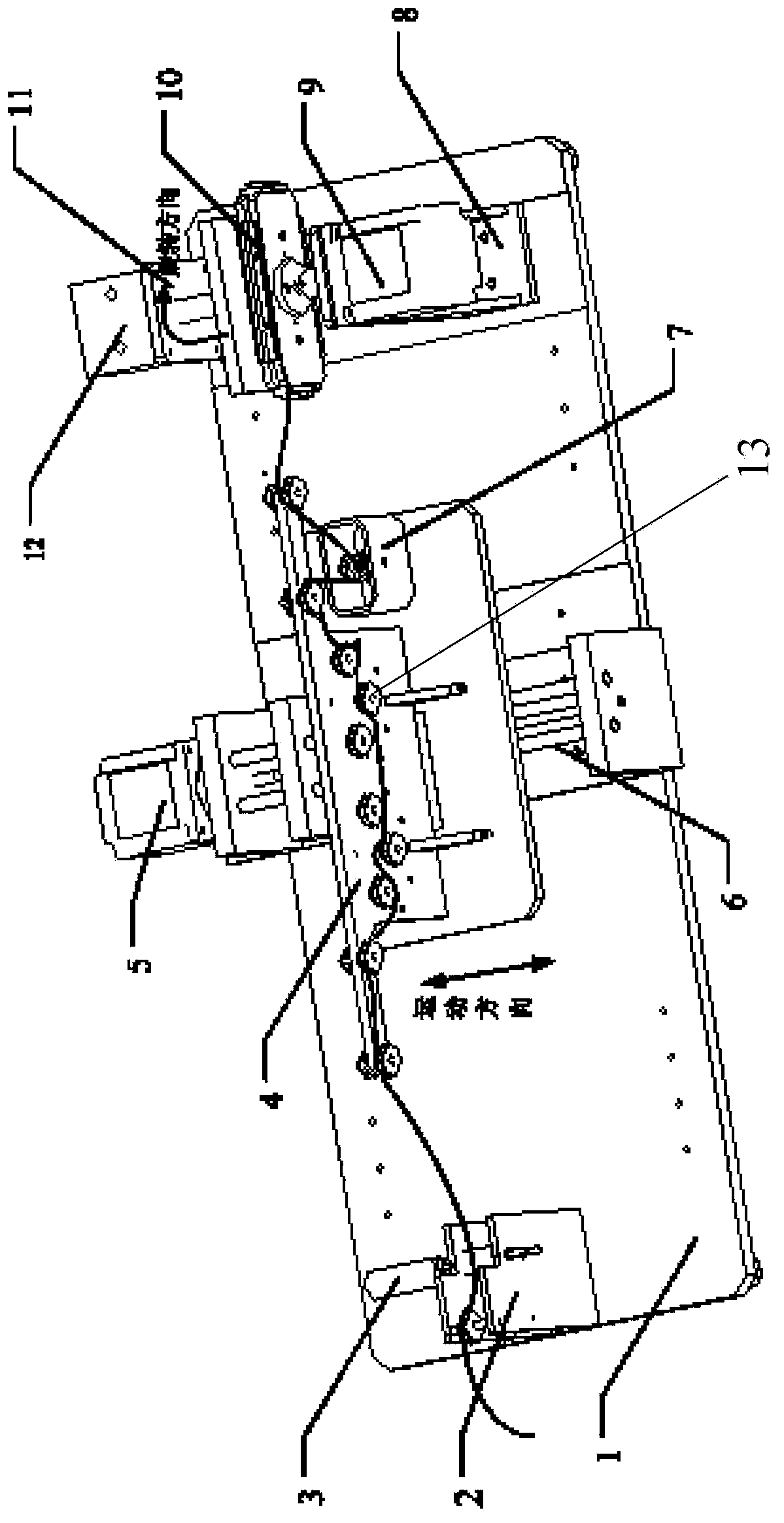
[0058] Please refer to figure 1 , the present embodiment provides a linear and planar motor coil winding device for winding flat or circular enameled wires, including a wire crimping device, a wire passing mechanism and a winding mechanism, and the wire passing mechanism Comprising a wire passing panel 4 and a wire passing wheel array 13, the winding mechanism includes a winding die 10 and a winding motor 9, the wire passing wheel array 13 is arranged on the surface of the passing wire panel 4, and the enameled wire passes through The crimping device is transferred to the wire passing wheel array 13, the enameled wire is passed to the winding die 10 through the wire passing wheel array 13, and the winding motor 9 drives the winding die 10 to rotate , the enameled wire is wound on the winding die 10 through the rotation of the winding die 10 .
[0059] The present invention can provide pre-tightening force for the transmission of the enameled wire by setting the wire crimping ...
Embodiment 2
[0087] Please refer to Figure 1 to Figure 6 , this embodiment provides another linear and planar motor coil winding method, using the linear and planar motor coil winding device provided in Embodiment 1 to wind flat enameled wire, when the enameled wire is delivered to the winding The wire model includes the following steps:
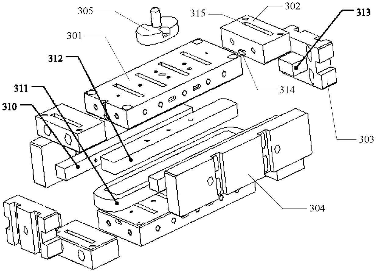
[0088] S201: Put the enameled wire close to the side of one of the winding substrates 301, wind the first coil around the winding post 312, and then pass the wire end through the outlet slot 309 and fix it with the winding screw 306 Connect; be about to wrap the wire end on the winding screw 306;
[0089] S202: By starting the winding motor 9 to make the winding mold 10 rotate, the enameled wire delivered to the winding mold 10 is wound on the winding column 312. During the winding process, the enameled wire is always The coil wound in the last turn is placed on the outer side of the coil of the previous turn perpendicular to the winding surface of the ...
Embodiment 3
[0097] The difference between this embodiment and embodiment 1 and embodiment 2 is that the mechanism of winding die 10 is slightly different, please refer to Figure 7 and Figure 8 , the winding die includes two winding substrates 501, the sides of the two winding substrates 501 are respectively provided with a raised part 502 and a slot 503, and the two winding substrates 501 pass the raised The parts 502 are mated and inserted into the slots 503 of each other to achieve connection, and are locked by fastening screws (not shown in the figure). The two raised parts 502 are combined to form a winding column for winding wires. There are outlet slots (not shown) for the enameled wires to pass through and winding screws (not shown) for fixing the ends of the enameled wires. In addition, the functions, shapes and coil winding methods of the components in Embodiments 1 and 2 are applicable to this embodiment. The structure adopted in this embodiment is simpler.
PUM
 Abstract
Description
Claims
Application Information