Linear and planar motor coil winding apparatus and method

A technology of planar motors and crimping devices, which is applied in the direction of electromechanical devices, manufacturing motor generators, electrical components, etc., can solve the problems of single-shaped coils in winding molds, low coil winding efficiency, and low application range, and achieve winding Accurate and effective effect

Active Publication Date: 2017-03-29
SHANGHAI MICRO ELECTRONICS EQUIP (GRP) CO LTD
View PDF5 Cites 8 Cited by
  • Summary
  • Abstract
  • Description
  • Claims
  • Application Information

AI Technical Summary

Problems solved by technology

[0006] 1. There is no positioning wire device, and the wire is easy to shake or shift during the transmission process, resulting in easy misalignment of coils or insufficient connection between turns;
[0007] 2. Manual winding and no position reference or device in the coil winding process, the coil winding efficiency is low and the dimensional accuracy is difficult to guarantee;
[0008] 3. The winding mold is only suitable for single-shaped coils and only round wires, and the scope of application is low

Method used


Image

  • Linear and planar motor coil winding apparatus and method
  • Linear and planar motor coil winding apparatus and method
  • Linear and planar motor coil winding apparatus and method

Examples


Embodiment 1

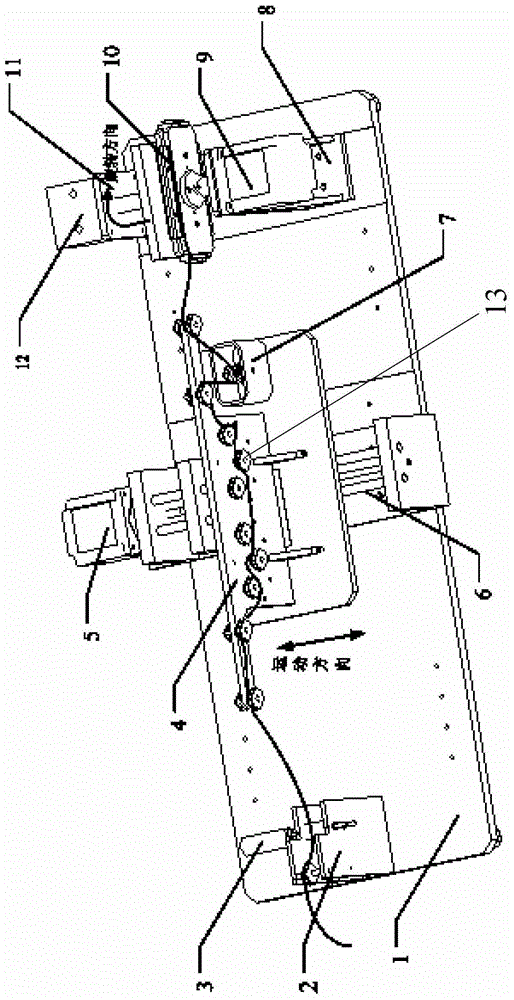
[0058] Please refer to figure 1 , This embodiment provides a linear and planar motor coil winding device for winding flat or round enameled wire, including a wire crimping device, a wire passing mechanism and a winding mechanism, the wire passing mechanism It includes a wire passing panel 4 and a wire passing wheel array 13. The winding mechanism includes a winding die 10 and a winding motor 9. The wire passing wheel array 13 is arranged on the surface of the wire passing panel 4, and the enameled wire passes The wire pressing device is transferred to the winding wheel array 13, the enameled wire is transferred to the winding die 10 through the 13 columns of the winding wheel array, and the winding motor 9 drives the winding die 10 to rotate , The enameled wire is wound on the winding die 10 through the rotation of the winding die 10.

[0059] Through the setting of the wire pressing device and the wire passing mechanism, the present invention can provide pre-tightening force for...

Embodiment 2

[0087] Please refer to Figure 1 to Figure 6 This embodiment provides another linear and planar motor coil winding method. The linear and planar motor coil winding device provided in Example 1 is used to wind the flat enameled wire. When the enameled wire is transferred to the winding The following steps are included in the line mold:

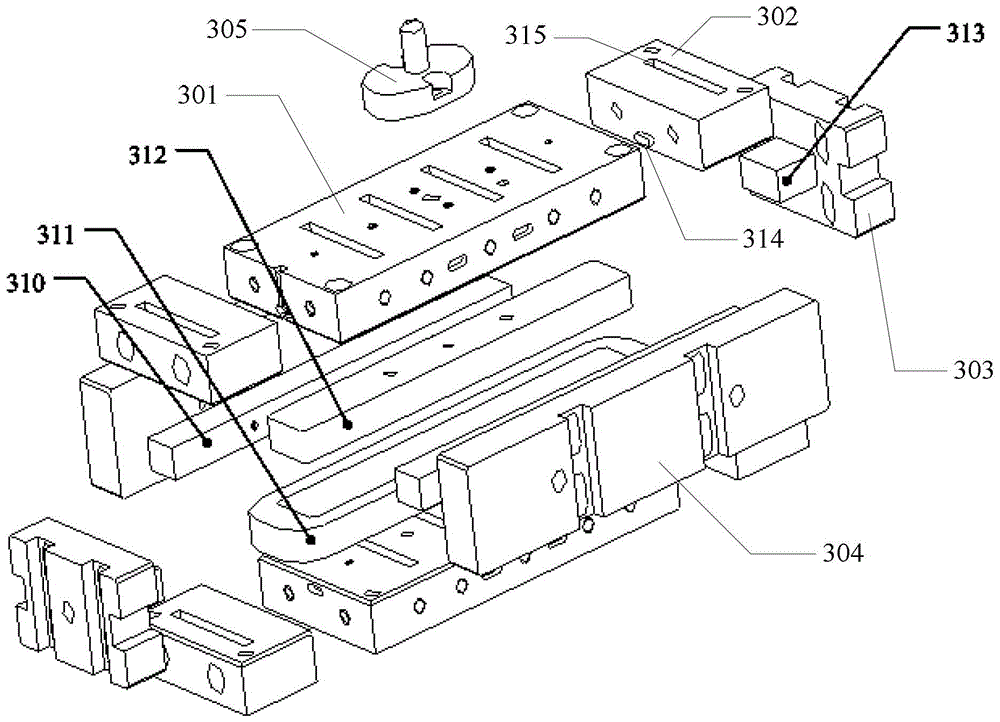
[0088] S201: Place the enameled wire close to the side surface of one of the winding substrates 301, wind the first turn of the coil around the winding post 312, and then pass the wire end through the wire outlet groove 309 to the winding screw 306 Connect; that is, the thread is wound on the winding screw 306;

[0089] S202: By starting the winding motor 9 to make the winding die 10 rotate, the enameled wire transferred to the winding die 10 is wound on the winding post 312, and during the winding process, always The coil wound by the latter turn is placed on the outer side of the former coil perpendicular to the winding surface of the bobbin 312...

Embodiment 3

[0097] The difference between this embodiment and embodiment 1 and embodiment 2 is only that the mechanism of winding die 10 is slightly different, please refer to Figure 7 versus Figure 8 The winding die includes two winding substrates 501. The sides of the two winding substrates 501 are provided with a protrusion 502 and a slot 503, respectively. The two winding substrates 501 The parts 502 are matched and inserted into the slots 503 of each other to realize the connection, and are locked by fastening screws (not shown). The two convex parts 502 are combined to form a winding post for winding, and the winding substrate 501 is provided There are outlet slots (not shown) for the enameled wire to pass through and winding screws (not shown) for fixing the end of the enameled wire. In addition, the functions, shapes and coil winding methods of the components in Embodiments 1 and 2 are all applicable to this embodiment. The structure adopted in this embodiment is simpler.


PUM


Abstract

The invention provides a linear and planar motor coil winding device for winding flat or circular varnished wires. The winding device comprises a wire-pressing device, a wire-passing mechanism and a winding mechanism. The wire-passing mechanism comprises a wire-passing panel and a wire-passing wheel array. The winding mechanism comprises a winding mould and a winding motor. The wire-passing wheel array is arranged on the surface of a wire-passing panel. The varnished wires are delivered to the wire-passing wheel array through the wire-pressing device; and the varnished wires are further delivered to the winding mould through the wire-passing wheel array. The winding motor drives the winding mould to rotate. The varnished wires are wound on the winding mould through the rotation of the winding mould. Through the arrangement of the wire-pressing device and the wire-passing mechanism, pretightening force is provided for the varnished wires, and thus the transmission speed of the varnished wires can be better controlled; and meanwhile, the winding motor is used to drive the winding mould to rotate so as to realize the winding of the varnished wires, and thus the defects of pure manual operation in the prior art are prevented.

Description

Technical field [0001] The invention relates to linear and planar motors in the semiconductor field, and more particularly to a linear and planar motor coil winding device and method. Background technique [0002] In recent years, planar motors have become a research hotspot in the semiconductor industry, and they are dedicated to researching smaller devices that include more functions and lower prices. With the advancement of science and technology, lithography systems develop and test extreme ultraviolet light sources. In order to prevent the pollution of optical components and the extreme ultraviolet light from being absorbed by air, the silicon wafers are exposed in a vacuum environment. A shorter wavelength light source is used for photolithography, and smaller features can be realized on each chip. The lithography machine is required to run fast, stable and accurate. It is bound to require the workpiece table to have a small quality, high rigidity and small interference. T...

Claims


Application Information

Patent Timeline
Patent Type & Authority Patents(China)
IPC IPC(8): H02K15/04
Inventor 刘小虎陈庆生段素丙
Owner SHANGHAI MICRO ELECTRONICS EQUIP (GRP) CO LTD
Why Eureka
Try Eureka