
Electric insulator cleaning device

A technology for cleaning devices and insulators, which is applied in the field of power systems and achieves good application prospects.

Active Publication Date: 2014-12-10
STATE GRID CORP OF CHINA +2
View PDF9 Cites 5 Cited by
  • Summary
  • Abstract
  • Description
  • Claims
  • Application Information

AI Technical Summary

Problems solved by technology

[0007] The present invention overcomes the problems of existing insulator cleaning mechanisms

Method used


Image

  • Electric insulator cleaning device
  • Electric insulator cleaning device

Examples


Embodiment Construction

[0020] The present invention will be further described below in conjunction with the accompanying drawings.

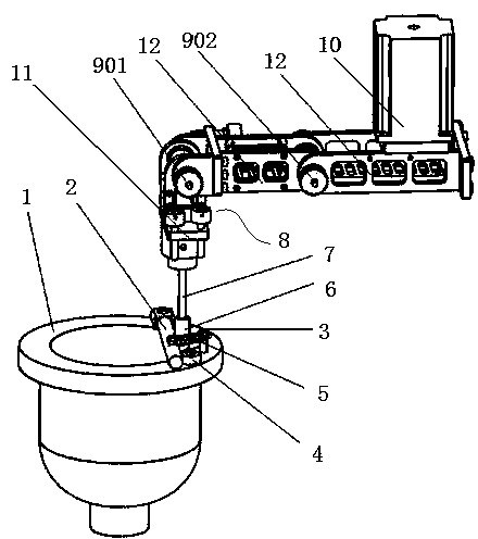
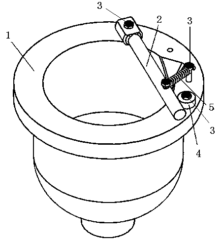
[0021] Such as figure 1 and figure 2 As shown, an insulator electric cleaning device includes a water tank 1, a connecting rod 2, a limit column 4, a tension spring 5, an electric cleaning head 6, a flexible shaft 7, an electric cleaning arm 8, a stepping motor 10, and a cleaning joint seat 11 Connect the joint seat 12 with the arm, the water tank 1 is used to collect the sewage when cleaning the insulator, and it is made of nylon plastic, which has good insulation and light weight. The sewage is used for the salt density detection of the insulator and for evaluating the regional environment The insulation performance of insulators in the medium and small power system and the safety performance of the power grid, and then scientifically guide and formulate the overhaul and maintenance plan of the power system. One end of the connecting rod 2 is fixed on the upper edg...


PUM


Abstract

The invention discloses an electric insulator cleaning device which comprises a water channel, a connecting rod, a limiting column, a tension spring, an electric cleaning head, a flexible shaft, an electric cleaning arm, a stepping motor, a cleaning joint seat and an arm connection joint seat. One end of the connecting rod is fixed on the upper edge of the water channel, the limiting column is arranged on the upper edge of the water channel and located at the other end of the connecting rod, the rod body of the connecting rod is fixedly connected with one end of the tension spring, the other end of the tension spring is fixed on the upper edge of the water channel, the tension spring enables the connecting rod to be tightly attached to the limiting column, the electric cleaning head is connected with a cleaning joint above the water channel through the flexible shaft, the electric cleaning arm is arranged on the upper portion of the cleaning joint seat, and the stepping motor is used for driving the electric cleaning arm to rotate. The electric insulator cleaning device can clean an insulator and collect dirt on the surface of the cleaning head, salt deposit density of an insulator can be obtained and used for assessing the insulating property of the insulator of an electrical power system in a regional environment and the safety performance of a power grid, and the electric insulator cleaning device has good application prospects.

Description

technical field [0001] The invention relates to an insulator electric cleaning device, which belongs to the technical field of power systems. Background technique [0002] During the operation of the power grid, due to the existence of various particles in the atmospheric environment, dirt such as dust is easy to accumulate on the surface of the insulator of the transmission line. Under normal circumstances, insulator flashover will occur under the operating voltage. In order to avoid the occurrence of pollution flashover accidents, the power system is usually overhauled regularly, and the dirt on the surface of the insulator is cleaned. The cleaning or anti-pollution flashover is determined according to the degree of pollution of the insulator. measure. At present, the cleaning of insulators in the power system is mainly manual cleaning, but cleaning insulators has problems such as heavy workload, high-altitude operations, and low cleaning efficiency. degree assessment. ...

Claims


Application Information

Patent Timeline
Patent Type & Authority Applications(China)
IPC IPC(8): B08B1/04
CPCB08B1/32
Inventor 刘洋陈杰路永玲高嵩马勇周志成
Owner STATE GRID CORP OF CHINA
Learn More