

Automotive mobile terminal clamping device
A mobile terminal and clamping device technology, which is applied in the direction of supporting machines, mechanical equipment, machine tables/supports, etc., can solve the problems of small adjustable range and inability to adapt to multiple types of mobile terminals, and achieve the effect of stable positioning
- Summary
- Abstract
- Description
- Claims
- Application Information
AI Technical Summary
Problems solved by technology
Method used
Image

Examples
Embodiment Construction
[0034] The preferred embodiments of the present invention will be described below in conjunction with the accompanying drawings. It should be understood that the preferred embodiments described here are only used to illustrate and explain the present invention, and are not intended to limit the present invention.
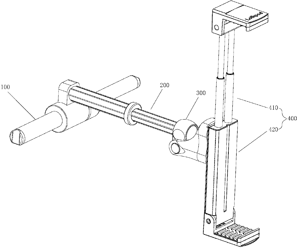
[0035] Such as Figure 1 to Figure 10 As shown, the vehicle mobile terminal clamping device of the present invention includes a clamping assembly 400, a fixing assembly 100, and a branch pipe assembly 200 for connecting the clamping assembly 400 and the fixing assembly 100, and the branch pipe assembly 200 passes through the pan / tilt assembly 300 is connected with clamping assembly 400 .
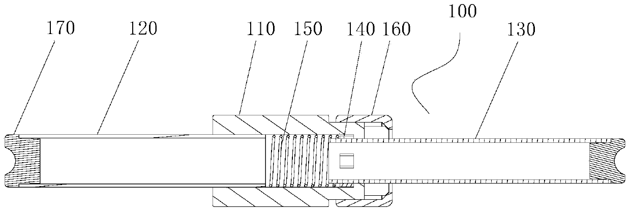
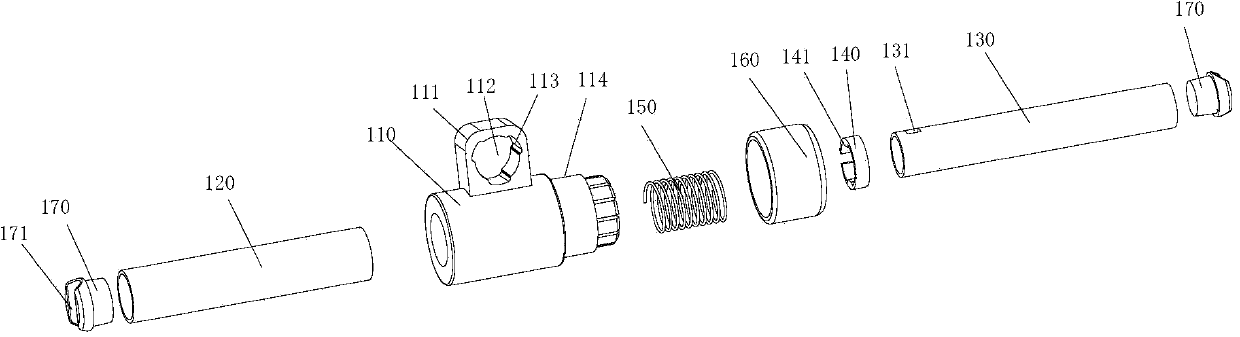
[0036] Such as Figure 2 ~ Figure 3 As shown, the fixed assembly 100 includes a connecting screw 110, a fixed rod 120 arranged at one end of the connecting screw 110, a movable rod 130 arranged at the other end of the connecting screw 110, and the connecting screw 110 is provided...
PUM
 Abstract
Description
Claims
Application Information