Extended cascade plasma gun

A plasma gun, neutral pole technology, applied in the field of ion guns, can solve the problems of few tests and lack of

Inactive Publication Date: 2014-12-10
SULZER METCO (US) INC
View PDF5 Cites 6 Cited by
  • Summary
  • Abstract
  • Description
  • Claims
  • Application Information

AI Technical Summary

Problems solved by technology

Lack of a clear understanding of the nature of the interaction between the gas and the arc during start-up and operation limits the ability to formulate solutions to the problem
Similar problems are expected in the neutral section of extended cascaded plasma guns and are rarely tested

Method used


Image

  • Extended cascade plasma gun

Examples


Embodiment Construction

[0027] The details shown here are by way of example only and discussions for the purpose of illustrating embodiments of the invention, and are presented in the course of providing what are believed to be the most useful and understandable description of the principles and concepts of the invention. In this regard, no attempt is made to show the structural details of the invention in more detail than is necessary for a basic understanding of the invention, and the description in conjunction with the accompanying drawings will make apparent to those skilled in the art several ways in which the invention can actually be embodied .

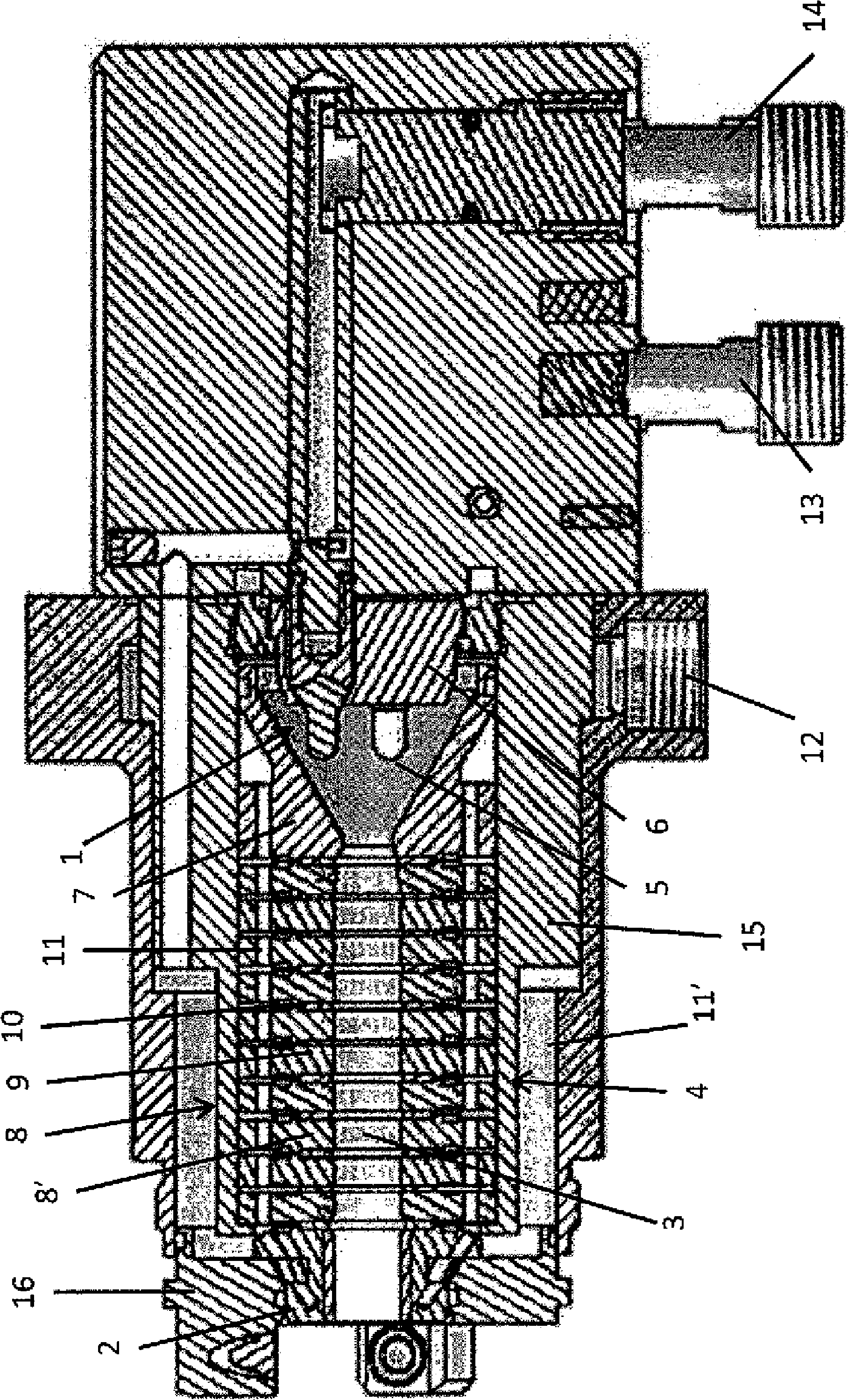
[0028] figure 1 The shown plasma spraying device comprises a cathode assembly 1 and an anode 2 separated by a plasma channel 3 defined by the annular interior of a neutral pole (neutrode) assembly 4 also called channel hole.

[0029] By way of non-limiting example, the cathode assembly 1 may comprise a plurality of cathodes 5, for example three cath...


PUM

PropertyMeasurementUnit
thicknessaaaaaaaaaa
thicknessaaaaaaaaaa
thicknessaaaaaaaaaa

Abstract

Plasma gun and method of applying powder to a substrate with a plasma gun. The plasma gun includes a cathode assembly (1), an anode (2), a rear neutrode (7), and an extended neutrode (8) positioned adjacent the rear neutrode (7) to define a channel bore (3) between the cathode assembly (1) and the anode (2). The extended neutrode (8) has a length greater than 38 mm. The plasma gun can also include at least one gas inlet to supply a gas to the channel bore (3) and a power supply.

Description

[0001] Cross References to Related Applications [0002] not applicable. [0003] Statement Regarding Federally Sponsored Research or Development [0004] not applicable. [0005] References to CD-ROM accessories [0006] not applicable. technical field [0007] The present invention relates to plasma guns and, in particular, to extended cascaded plasma guns for plasma spray deposition of powders onto substrates. Background technique [0008] When developing plasma guns, designers and engineers try to achieve the highest possible gun voltage to allow high power levels while maintaining the lowest possible current. Conventional plasma guns have limited voltage capability due to gun geometry, and use high potential assist gases to increase voltage and to increase other plasma characteristics, such as high enthalpy. [0009] The ability to prolong the cascade of the plasma arc within the plasma gun is limited by the total potential to complete the arc circuit from cathode ...

Claims


Application Information

Patent Timeline
Patent Type & Authority Applications(China)
IPC IPC(8): B23K9/24
CPCH05H2001/3452H05H1/34H05H1/42C23C4/127H05H1/3452C23C4/134
Inventor R.J.莫尔兹D.霍利R.麦库劳格
Owner SULZER METCO (US) INC
Why Eureka
Try Eureka