
A hinge that is easy to disassemble

A convenient disassembly and hinge technology, applied in door/window fittings, hinged panels, buildings, etc., can solve the time-consuming and labor-intensive disassembly, damage to the panel coating at the joint, and the operator's hinge support is connected with the door panel and the cabinet or box Position misalignment and other problems, to achieve the effect of firm connection and easy disassembly

Active Publication Date: 2016-03-30
WSELE ELECTRICAL
View PDF7 Cites 0 Cited by
  • Summary
  • Abstract
  • Description
  • Claims
  • Application Information

AI Technical Summary

Problems solved by technology

[0002] At present, the non-detachable hinge has a wide range of applications, and the inconvenience it brings is that when the door panel needs to be disassembled, it is necessary to take out the rivets, screws, and bolts used to fix the hinge support or crack the connecting solder joints. Not only is it time-consuming and laborious to disassemble, but it will also damage the panel coating at the joint. After the coating is damaged, the anti-rust performance of the metal cabinet body and / or box body and door panels will be greatly reduced, and the operator is random and unprofessional during disassembly and installation. It will make the position of the hinge support connected to the door panel and the cabinet body or the box body misplaced or the original position is difficult to re-align, and the closure of the door panel to the cabinet body or box body will be affected.

Method used


Image

  • A hinge that is easy to disassemble
  • A hinge that is easy to disassemble
  • A hinge that is easy to disassemble

Examples


Embodiment Construction

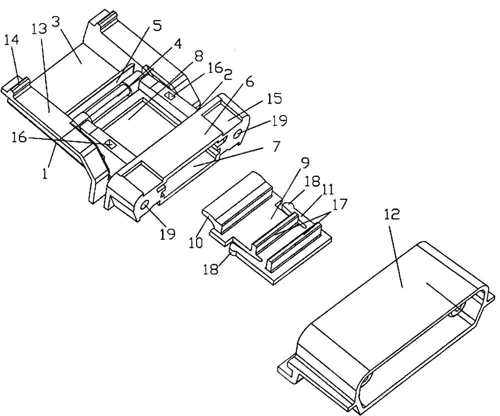
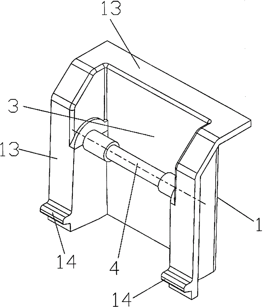
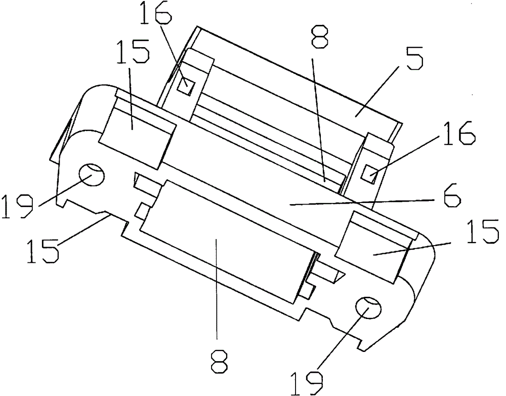
[0014] please see Figure 1 to Figure 4 A hinge that is easy to disassemble is shown, including a first hinge support 1 and a second hinge support 2, the first hinge support 1 is provided with a through groove 3, and a fixed shaft is arranged between the two side walls of the through groove 3 4. The diameters of the shaft sections at both ends of the fixed shaft 4 are equal and greater than the diameter of the shaft section in the middle of the fixed shaft 4. There is a gap between the fixed shaft 4 and the bottom of the through groove 3. One end of the second hinge support 2 is provided with a The fixed shaft 4 rotates the hook 5 that is socketed, and the other end of the second hinge support 2 is provided with a sleeve joint 6, and the end surface of the sleeve joint 6 is provided with a through hole 7, and the through hole 7 is opened on the hook 5 and the sleeve joint. The clamping slots 8 between the 6 are connected, and the clamping slot 8 is clamped with a hook anti-off...


PUM


Abstract

The invention discloses a conveniently-detached hinge. The conveniently-detached hinge comprises a first hinge support and a second hinge support, wherein a through groove is formed in the first hinge support and a fixed shaft is arranged between two side walls of the through groove; the diameters of shaft sections at the two ends of the fixed shaft are greater than the diameter of a shaft section in the middle of the fixed shaft; a gap is formed between the fixed shaft and the bottom of the through groove; a clamping hook which is rotationally connected with the fixed shaft in a sleeving manner is arranged at one end part of the second hinge support; a sleeving connector is arranged at the other end of the second hinge support and a through hole is formed in the end face of the sleeving connector and is communicated with a clamping groove formed between the clamping hook and the sleeving connector; the clamping groove is internally clamped with a clamping hook anti-releasing fixing block; a circular-arc stopping block matched with an opening of the clamping hook is arranged at the front end of the clamping hook anti-releasing fixing block. According to the conveniently-detached hinge, the hinge supports do not need to be detached when a door plate is detached, and a fixed connection position and surface plating layers between the supports and the door plate and / or a box / a cabinet body are not damaged; the hinge is convenient to detach and is firmly connected through the clamping hook anti-releasing fixing block.

Description

technical field [0001] The invention relates to the technical field of manufacturing electric meter boxes and power distribution cabinets, in particular to a conveniently detachable hinge connected between a cabinet body and / or a box body and a door panel. Background technique [0002] At present, the non-detachable hinge has a wide range of applications, and the inconvenience it brings is that when the door panel needs to be disassembled, it is necessary to take out the rivets, screws, and bolts used to fix the hinge support or crack the connecting solder joints. Not only is it time-consuming and laborious to disassemble, but it will also damage the panel coating at the joint. After the coating is damaged, the anti-rust performance of the metal cabinet body and / or box body and door panels will be greatly reduced, and the operator is random and unprofessional during disassembly and installation. All will make the joint position of the hinge support and the door panel and the...

Claims


Application Information

Patent Timeline
Patent Type & Authority Patents(China)
IPC IPC(8): E05D7/12
Inventor 郑元海陈晓柱倪飞远郑武彭龙精
Owner WSELE ELECTRICAL
Learn More