Excitation device with longitudinal magnetic field for medium-frequency current test system
A technology of longitudinal magnetic field and intermediate frequency current, which is applied in the direction of high voltage/high current switch, circuit, electric switch, etc., and can solve the problem that the influence of magnetic field change on arc cannot be analyzed.
- Summary
- Abstract
- Description
- Claims
- Application Information
AI Technical Summary
Problems solved by technology
Method used
Image
Examples
Embodiment 1
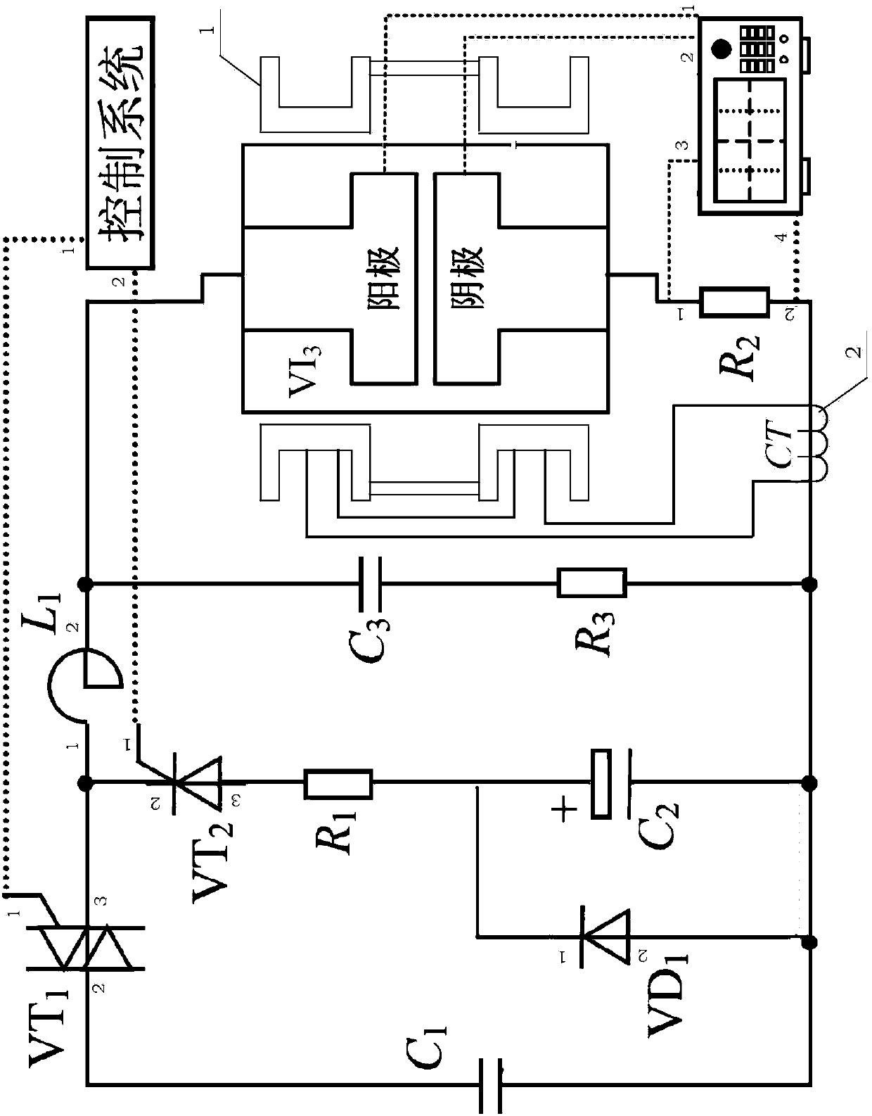
[0056] The current frequency is 400Hz, and a current transformer is set. Then the relationship between the voltage and the experimental time is as follows: Figure 4 shown. In the figure, the ordinate is the shunt R 2 The voltage at both ends of , and the abscissa is the experimental time. The peak value of the first half wave of the primary current is 11.3kA, which is the shunt R 2 The voltage value across the shunt divided by the R 2 The resistance value is 1.2mΩ.
[0057] The relationship between the magnetic induction intensity of the longitudinal magnetic field and the experimental time is as follows: Figure 4A shown. In the figure, the ordinate is the magnetic induction intensity of the longitudinal magnetic field at the axis center of the Helmholtz coil, and the abscissa is the experiment time. The peak value of the first half wave is 46.1mT.
Embodiment 2
[0059] The current frequency is 400Hz, and two current transformers are set. Then the relationship between the voltage and the experimental time is as follows: Figure 5 shown. In the figure, the ordinate is the shunt R 2 The voltage at both ends of , and the abscissa is the experimental time. The peak value of the first half wave of the primary current is 10.7kA, which is the shunt R 2 The voltage value across the shunt divided by the R 2 The resistance value is 1.2mΩ.
[0060] The relationship between the magnetic induction intensity of the longitudinal magnetic field and the experimental time is as follows: Figure 5A shown. In the figure, the ordinate is the magnetic induction intensity of the longitudinal magnetic field at the center of the Helmholtz coil axis, and the abscissa is the experiment time. The peak value of the first half wave is 87.2mT.
Embodiment 3
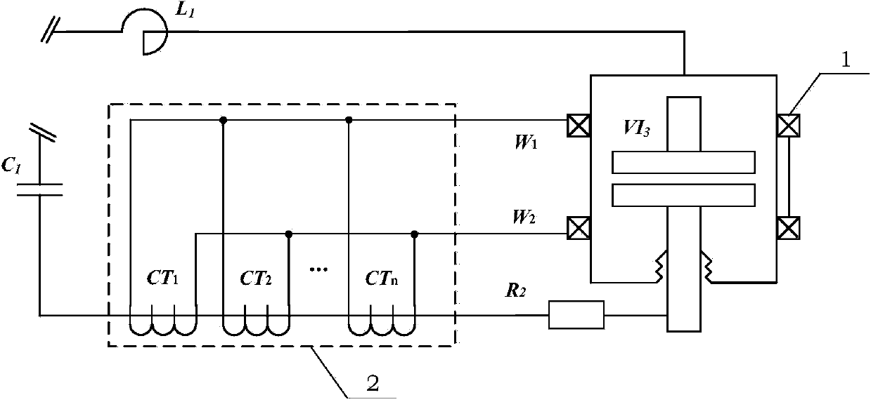
[0062] The current frequency is 800Hz, and 6 current transformers are set. Then the relationship between the voltage and the experimental time is as follows: Figure 6 shown. In the figure, the ordinate is the shunt R 2 The voltage at both ends of , and the abscissa is the experimental time. The peak value of the first half wave of the primary current is 15.9kA, which is the shunt R 2 The voltage value across the shunt divided by the R 2 The resistance value is 1.2mΩ.
[0063] The relationship between the magnetic induction intensity of the longitudinal magnetic field and the experimental time is as follows: Figure 6A shown. In the figure, the ordinate is the magnetic induction intensity of the longitudinal magnetic field at the center of the Helmholtz coil axis, and the abscissa is the experiment time. The peak value of the first half wave is 395.8mT.
[0064] Optimizing the Contact Structure of Vacuum Interrupter
[0065] The medium-frequency vacuum arc experiment ...
PUM
 Abstract
Description
Claims
Application Information
 - R&D
- Intellectual Property
- Life Sciences
- Materials
- Tech Scout
- Unparalleled Data Quality
- Higher Quality Content
- 60% Fewer Hallucinations
Browse by: Latest US Patents, China's latest patents, Technical Efficacy Thesaurus, Application Domain, Technology Topic, Popular Technical Reports.
© 2025 PatSnap. All rights reserved.Legal|Privacy policy|Modern Slavery Act Transparency Statement|Sitemap|About US| Contact US: help@patsnap.com


