Superconducting magnetic separator

A superconducting magnetic and electromagnetic technology, which is applied in the field of superconducting electromagnetic beneficiation equipment or superconducting electromagnetic equipment for removing metal or metal compounds, can solve the problems of high magnetic field gradient, complex structure of superconducting electromagnetic separator, and low utilization rate

Active Publication Date: 2010-05-12
YONGFENG BOYUAN IND CO LTD JIANGXI PROVINCE
View PDF1 Cites 10 Cited by
  • Summary
  • Abstract
  • Description
  • Claims
  • Application Information

AI Technical Summary

Problems solved by technology

On the one hand, because ferromagnetic materials can reach magnetic saturation when the background magnetic field is about 1.2T, increasing the background magnetic field strength cannot produce a higher magnetic field gradient; on the other hand, the existing magnetic separators use the edge of the magnetic field part, its magnetic induction field strength decreases exponentially, and the utilization rate is low
When the magnetic induction intensity of the working magnetic field is within 1.2T, it can only suck out substances with strong magnetism and medium strength magnetism, but cannot suck out titanium, vanadium, tungsten, chromium, manganese, nickel, gold, silver, lead, zinc, mercury, Arsenic, cobalt, molybdenum and many other metals and rare precious metals or their compounds, and low content of hematite and ferrous oxide and other substances
[0004] In addition, the existing superconducting electromagnetic separator has a relatively complex structure, which is not conducive to installation and maintenance

Method used


Image

  • Superconducting magnetic separator
  • Superconducting magnetic separator
  • Superconducting magnetic separator

Examples


Embodiment Construction

[0017] A superconducting electromagnetic separator of the present invention will be described below in conjunction with specific embodiments. The described embodiments are for better illustration of the present invention, and should not be construed as limitations on the claims of the present invention.

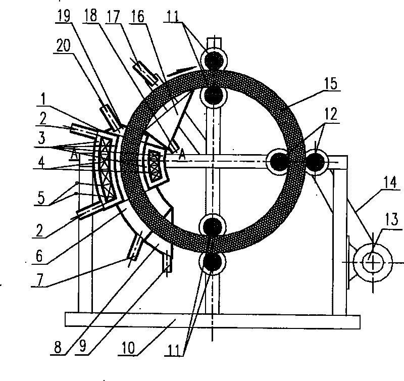
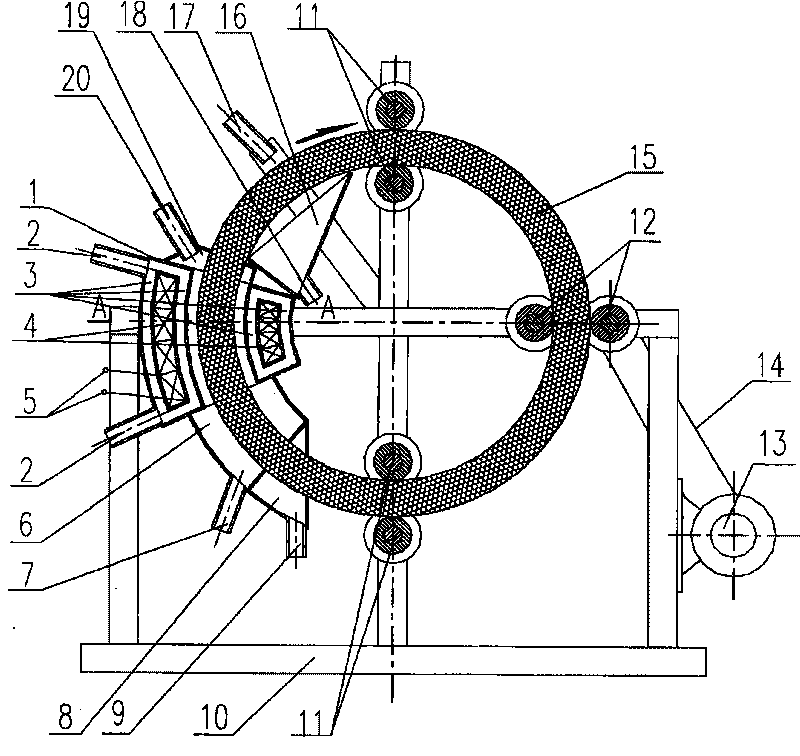
[0018] Implementations such as figure 1 Shown is a schematic diagram of the structure of a superconducting electromagnetic separator. The structure of the superconducting electromagnetic separator consists of a superconducting magnetic system, a magnetic wire drum 15, a magnetic wire drum positioning system, a magnetic wire drum driving system, a superconducting electromagnetic separator bracket 10, a feed trough 19, and a dispersed selection tank. 6. It is composed of the tailings collection tank 8 and the extract recovery system.

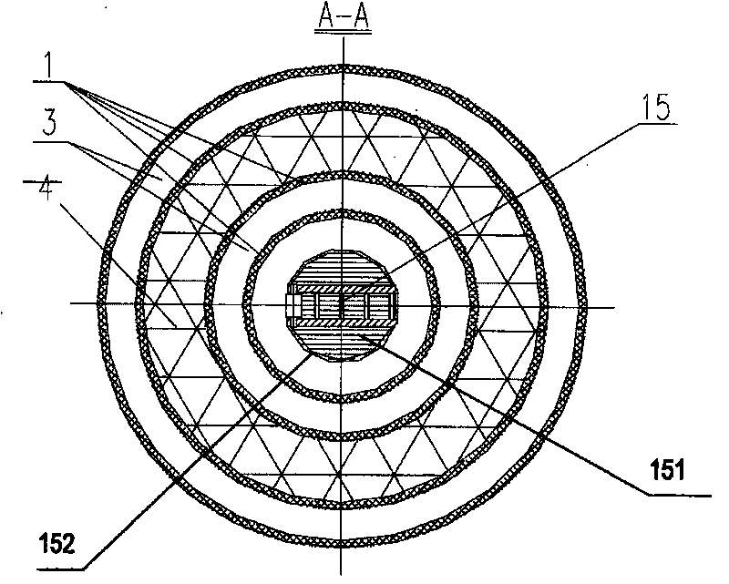
[0019] The superconducting magnetic system includes a superconducting magnetic system housing 1 and a magnetic core coil 4; 2 to 4 short tubes ...


PUM


Abstract

The invention provides a superconducting magnetic separator which comprises a superconducting magnetic system, a magnetic wire rotary drum (15), a positioning system of the magnetic wire rotary drum, a driving system of the magnetic wire rotary drum, a support (10) of the superconducting magnetic separator and the like. The superconducting magnetic system comprises a housing (1) of the superconducting magnetic system and a magnetic core coil (4), and the magnetic core coil (4) is wrapped by the housing (1) of the superconducting magnetic system; the magnetic wire rotary drum (15) is positioned on the support (10) of the superconducting magnetic separator by the positioning system of the magnetic wire rotary drum, and the magnetic wire rotary drum (15) penetrates the center of the superconducting magnetic system and can rotate freely around the point of the center of a circle under the driving of the driving system of the magnetic wire rotary drum. The superconducting magnetic separator utilizes the central part with the strongest magnetic field intensity in the superconducting magnetic system, fully utilizes the energy of a magnetic field and the electrical energy, and can better separate and sort a variety of components with different magnetisms in ores; furthermore, the superconducting magnetic separator has convenient mounting, easy control and easy maintenance and can avoid the interferences of the magnetic field. The superconducting magnetic separator can also be applied in foods, biotechnology, pharmaceutical industry, medicine, medical industry and other fields.

Description

technical field [0001] The present invention relates to a superconducting electromagnetic beneficiation equipment or superconducting electromagnetic equipment for removing metal or metal compounds, especially a superconducting electromagnetic separator for sorting weak magnetic, weak magnetic, extremely weak magnetic and paramagnetic substances and / or Or adjustable superconducting electromagnetic separator. The superconducting electromagnetic separator can also be used in the fields of food, biology, pharmacy, medicine and medical treatment to remove harmful lead, zinc, mercury, arsenic, Cobalt, molybdenum, chromium, manganese, nickel and other metals and heavy metals or their compounds. Background technique [0002] Due to the rapid development and transformation of science, technology, and social and economic activities, the mining and consumption of mineral resources have increased rapidly, and the proven reserves of various rich ores have become less and less. If the po...

Claims


Application Information

Patent Timeline
Patent Type & Authority Applications(China)
IPC IPC(8): B03C1/14
Inventor 魏雄辉
Owner YONGFENG BOYUAN IND CO LTD JIANGXI PROVINCE
Why Eureka
Try Eureka