Motor rotor pressing plate

A motor rotor and pressure plate technology, applied in the direction of magnetic circuit rotating parts, magnetic circuit shape/style/structure, etc., can solve the problems of cumbersome operation of the rotor pressure plate, accumulation of tolerances in installation, etc., to solve the complicated assembly, prevent grease leakage, The effect of efficient assembly

Inactive Publication Date: 2014-12-17
CRRC YONGJI ELECTRIC CO LTD
View PDF5 Cites 7 Cited by
  • Summary
  • Abstract
  • Description
  • Claims
  • Application Information

AI Technical Summary

Problems solved by technology

[0003] The present invention provides an electronic rotor press plate in order to solve the technical problems of cumbersome operation and accumulation of installation tolerances in the current rotor press plate during use and assembly.

Method used


Image

  • Motor rotor pressing plate
  • Motor rotor pressing plate

Examples


Embodiment Construction

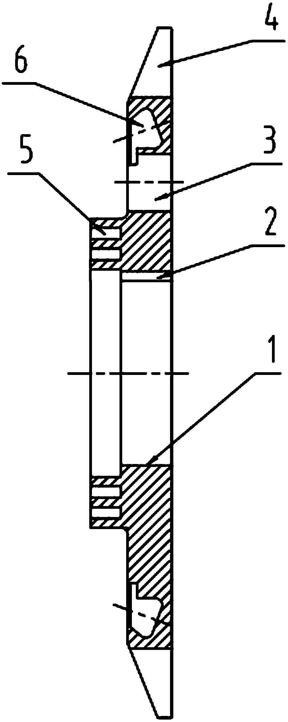
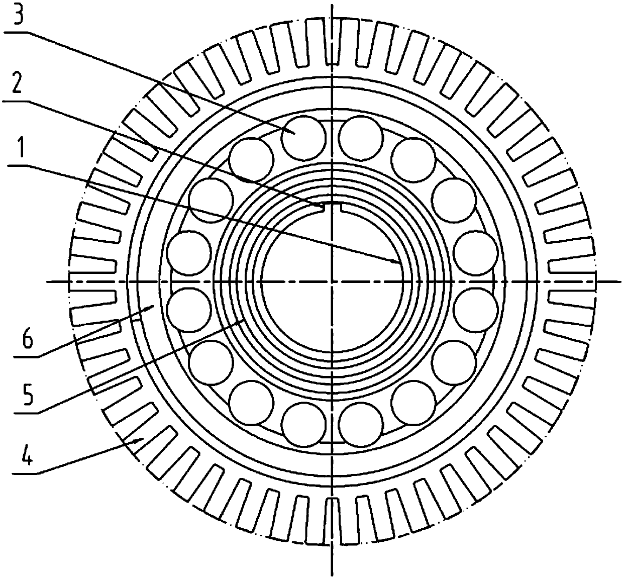
[0012] A motor rotor pressure plate, the center of the pressure plate is provided with a mounting shaft hole 1, and the outer circumference of the pressure plate is evenly distributed with pressure plate teeth 4; the upper part of the mounting shaft hole 1 is provided with a positioning keyway 2 for fixed connection with the iron core punch, and the mounting shaft hole 1 Ventilation holes 3 are evenly distributed on the outer circumference of the outer circle; an oil seal labyrinth 5 is provided on the circumference of the pressure plate between the ventilation holes 3 and the installation shaft hole 1, and an annular balance groove 6 is arranged on the periphery of the ventilation hole 3 on the pressure plate .

[0013] The size of the pressing plate teeth 4 provided on the rotor pressing plate is smaller than the supporting iron core teeth, which can avoid interference during the assembly of the rotor squirrel cage.

[0014] The ventilation hole 3 provided on the rotor press...


PUM


Abstract

The invention relates to the manufacturing field of a motor and specifically discloses a motor rotor pressing plate. Through the motor rotor pressing plate, the technical problem of complex operation and installation tolerance accumulation during assembling is solved in the present rotor pressing plate. The motor rotor pressing plate is characterized in that a pressing plate center is provided with an installing axle hole, and pressing plate gears are uniformly arranged around the outer edge of the pressing plate; the upper part of the installing axle hole is provided with a positioning key slot fixedly connected with a core stamping sheet, and ventilation holes are uniformly arranged around the outside of the installing axle hole; the pressing plate positioned between the ventilation hole and the installing axle hole is provided with an oil seal maze, and the pressing plate at the periphery of the ventilation hole is provided with an annular balancing slot. To the motor rotor pressing plate, by increasing the thickness of the pressing plate and arranging the balancing slot and the oil seal maze, the rotor pressing plate can simultaneously compress the core stamping sheet, execute dynamic balance and prevent oil from leakage, thereby simplifying the compressing, dynamic balance and oil seal structure of the motor and the manufacturing process and solving the problem of complex assembling and weak uniformity in use.

Description

technical field [0001] The invention relates to the field of motor manufacturing, in particular to a motor rotor pressure plate. Background technique [0002] At present, in the design of the motor, in order to prevent the problems of tooth expansion or loosening of the rotor core of the motor, a thin steel plate with ventilation holes and pressure plate teeth is installed at both ends of the rotor core as the rotor pressure plate. When the rotor is stacked, After aligning it with the iron core, press it tightly and fix it. In addition, since the rotor of the motor is a high-speed rotating part, dynamic balancing of the rotor is required. Usually, a balance disc is installed on each end of the rotor shaft for dynamic balancing to prevent motor vibration and reduce bearing damage. Usually, the shafts inside the bearings at both ends of the motor also need to be provided with oil seals to prevent the leakage of bearing grease, and several layers of labyrinths are arranged on ...

Claims


Application Information

Patent Timeline
Patent Type & Authority Applications(China)
IPC IPC(8): H02K1/22
Inventor 尚前博张彩霞李文科庞聪吕杰薛秀慧胡彬
Owner CRRC YONGJI ELECTRIC CO LTD
Why Eureka
Try Eureka