Middle-large sized motor stator and rotor anti-gear swelling iron core

A large-scale motor, stator and rotor technology, applied in the direction of electric components, electrical components, electromechanical devices, etc., can solve the problems of difficulty in ensuring the pressing force and tooth expansion requirements at the same time, affecting the overall performance of the motor, and high manufacturing costs. The effect of shortening the length and improving the performance of the motor

Inactive Publication Date: 2016-08-10
CRRC YONGJI ELECTRIC CO LTD
View PDF8 Cites 0 Cited by
  • Summary
  • Abstract
  • Description
  • Claims
  • Application Information

AI Technical Summary

Problems solved by technology

[0003] The invention solves the problems that the stator and rotor iron cores of the existing medium and large motors are difficult to ensure the pressing force and tooth expansion requirements at the same time, the manufacturing cost is high, the processing is difficult, and the overall performance of the motor is affected, and it provides a medium and large motor stator and rotor tooth expansion prevention iron core

Method used


Image

  • Middle-large sized motor stator and rotor anti-gear swelling iron core
  • Middle-large sized motor stator and rotor anti-gear swelling iron core
  • Middle-large sized motor stator and rotor anti-gear swelling iron core

Examples


Embodiment Construction

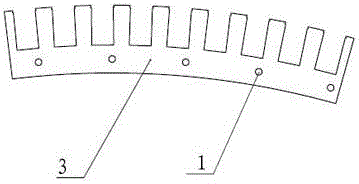
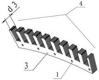
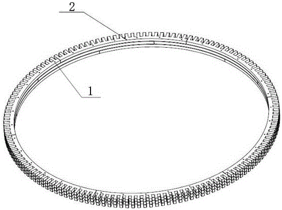
[0011] The stator and rotor anti-tooth expansion iron core of medium and large motors includes a laminated silicon steel sheet body. A connecting hole 1 is opened on the silicon steel sheet body, and a connecting rod is pierced in the connecting hole 1. The silicon steel sheet body is composed of The self-adhesive silicon steel sheet body 2 is composed of a non-self-adhesive silicon steel sheet in the middle, and after the self-adhesive silicon steel sheet body 2 is spliced ​​into a full circular self-adhesive silicon steel sheet layer by the self-adhesive silicon steel sheet group 4, more The layers are stacked with staggered seams, and the self-adhesive silicon steel sheet group 4 is formed by laminating and bonding arc-shaped self-adhesive silicon steel sheet units 3 coated with a self-adhesive coating on the multi-layer surface. The connection holes 1 are opened on each self-adhesive silicon steel sheet unit 3, and the self-adhesive silicon steel sheet groups 4 are laminate...


PUM

PropertyMeasurementUnit
thicknessaaaaaaaaaa

Abstract

The invention relates to a motor stator and rotor iron core, concretely a middle-large sized motor stator and rotor anti-gear swelling iron core, and aims to solve the problems that a present stator and rotor iron core can not meanwhile guarantee compacting force and gear swelling requirements, is high in cost and difficult to process, and influences motor whole performance. In the scheme, the iron core comprises a silicon steel plate body which is provided with connection apertures, and connecting rods penetrate the connection apertures; the body is composed of self-bonded silicon steel plate bodies at two ends and a non self-bonded silicon steel plate at the central section; the silicon steel plate is assembled into a circular silicon steel plate layer through a self-bonded silicon steel plate set, and is then laminated and staggered; the silicon steel plate set is formed by laminating and bonding a plurality of layers of silicon steel plate units; the silicon steel plate units are provided with connection apertures; the silicon steel plate set realizes lamination connection through holes and rods. The iron core has the following advantages: first, the silicon steel plate body is used as an effective electromagnetic material, effectively compresses a gear portion and avoids gear swelling; second, the iron core is compressed as a whole, thereby avoiding unstable operation and large noise, and improving motor performance; and third, the iron core has a simplified structure, shortens the end portion length of a coil, reduces costs, and improves motor performance.

Description

technical field [0001] The invention relates to a motor stator and rotor iron core, in particular to a middle and large motor stator and rotor tooth expansion prevention iron core. Background technique [0002] The stator and rotor iron core of the motor is laminated by a certain number of silicon steel sheets into a whole iron core. In the prior art, the compression method of the iron core is to initially laminate the silicon steel sheets, and then use screw tightening or riveting or iron mandrel welding; a special finger-shaped pressing plate can also be designed for compression. But above-mentioned two kinds of methods all have certain defect: 1, adopt screw rod to tighten up or riveting or iron mandrel welding compaction, because the scattered distribution of fastening point position can't reach the complete coincidence between silicon steel sheet and sheet, make silicon steel sheet The interlayer resistance between the sheet and the sheet increases, thus causing the mo...

Claims


Application Information

Patent Timeline
Patent Type & Authority Applications(China)
IPC IPC(8): H02K1/14H02K1/24
CPCH02K1/146H02K1/24H02K2201/09H02K2213/03
Inventor 朱红燕周会军王成王裕峰安康平
Owner CRRC YONGJI ELECTRIC CO LTD
Why Eureka
Try Eureka