Positioning tool for welding transformer tank

A technology for welding transformers and positioning tooling, which is applied in welding equipment, auxiliary welding equipment, welding/cutting auxiliary equipment, etc., and can solve problems such as difficulty in ensuring welding quality and reducing welding efficiency

Active Publication Date: 2014-12-24
河北昊昱焊接技术研究所有限公司
View PDF10 Cites 6 Cited by
  • Summary
  • Abstract
  • Description
  • Claims
  • Application Information

AI Technical Summary

Problems solved by technology

[0002] Transformers are widely used in production. The transformer is a device that uses the principle of electromagnetic induction to change the AC voltage. The oil tank is an important part of the transformer. The transformer oil tank includes an outer shell and a corrugated plate. The outer shell is welded by steel plates. Its structure In addition to having a certain mechanical strength and meeting some requirements of the transformer during operation, it should also meet some necessary conditions during the maintenance and transportation of the transformer. The corrugated board is a corrugated sheet, and the side protruding outwards has peaks and troughs. , can increase the heat dissipation surface of the transformer oil. The corrugated sheets are welded on the wall of the transformer oil tank. When welding the shell of the transformer oil tank and the corrugated plate, there is often no suitable positioning tool, and the welding experience of the welder can only be relied on. Straightening and positioning is not only difficult to guarantee the welding quality, but also greatly reduces the welding efficiency

Method used


Image

  • Positioning tool for welding transformer tank
  • Positioning tool for welding transformer tank

Examples


Embodiment Construction

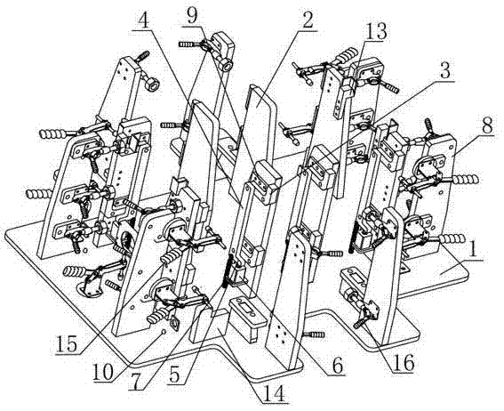
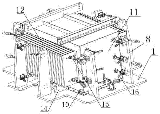
[0013] Such as figure 1 Shown is a schematic structural diagram of the tooling, including a base plate 1, on which an inner positioning mechanism and an outer positioning mechanism are provided. The inner positioning mechanism is: a plurality of vertically arranged first fixing plates 2 are arranged in the middle of the base plate 1 , on the side wall of each first fixed plate 2, there is a horizontal "7" shape body 3, and the position where the horizontal section and the vertical section of the horizontal "7" shape body 3 are connected is connected with the first rotating shaft. The first fixed plate 2 is hinged, the vertical section of the horizontal "7" shape body 3 is located on the side near the edge of the bottom plate 1, the vertical section is located on the upper side of the horizontal section, and the inner end of the horizontal section passes through The second rotating shaft is hinged with the vertical rod 4, the bottom end of the vertical rod 4 is connected with a...


PUM


Abstract

The invention discloses a positioning tool for welding a transformer tank, and relates to the technical field of welding and positioning tools. The positioning tool comprises a bottom plate, wherein an inner side positioning mechanism and an outer side positioning mechanism are arranged on the bottom plate. The inner side positioning mechanism is as follows: a plurality of first fixing plates which are vertically arranged are arranged on the bottom plate; a 7-shaped body is arranged on each first fixing plate, and is hinged with each first fixing plate through a first rotating shaft; the vertical section of each 7-shaped body is arranged at one side close to the side of the bottom plate, and is arranged at the upper side of a transverse section; the inner end of the transverse section is hinged with a vertical bar; the bottom end of the vertical bar is connected with a cross bar; the cross bar is connected with a piston rod of a cylinder; the bottom end of the vertical bar is also connected with a spring. The outer side positioning mechanism is as follows: a plurality of second fixing plates which are arranged along the extension direction of the side of the bottom plate are arranged on the edge of the bottom plate; and quick clamps are arranged on the second fixing plates. The tool is capable of quickly positioning an oil tank side plate to be welded, so that the welding is quick and accurate, and is carried out in place.

Description

technical field [0001] The invention relates to the technical field of welding positioning tools. Background technique [0002] Transformers are widely used in production. The transformer is a device that uses the principle of electromagnetic induction to change the AC voltage. The oil tank is an important part of the transformer. The transformer oil tank includes an outer shell and a corrugated plate. The outer shell is welded by steel plates. Its structure In addition to having a certain mechanical strength and meeting some requirements of the transformer during operation, it should also meet some necessary conditions for the maintenance and transportation of the transformer. The corrugated board is a corrugated sheet, and the side protruding outwards has peaks and troughs. , can increase the heat dissipation surface of the transformer oil. The corrugated sheets are welded on the wall of the transformer oil tank. When welding the outer shell of the transformer oil tank and...

Claims


Application Information

Patent Timeline
IPC IPC(8): B23K37/04
CPCB23K37/0435
Inventor 崔连森叶光昱武剑石宁
Owner 河北昊昱焊接技术研究所有限公司
Why Eureka
Try Eureka